Form No. 3428-559 Rev A 60in Blower Kit Groundsmaster® 360 and 7200 Series Tripple Bagger Hopper Model No. 31213—Serial No. 402620001 and Up Installation Instructions WARNING CALIFORNIA Proposition 65 Warning Use of this product may cause exposure to chemicals known to the State of California to cause cancer, birth defects, or other reproductive harm.
Loose Parts Use the chart below to verify that all parts have been shipped. Procedure 1 2 3 4 5 6 7 8 9 10 11 Description Qty. Use No parts required – Prepare the machine. Double pulley assembly 1 Install the pulley assembly. No parts required – Remove the existing anti-scalp roller and bracket (for 60-inch decks only).
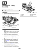
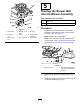
2 Installing the Pulley Assembly Parts needed for this procedure: 1 Double pulley assembly Procedure g033896 Figure 2 1. Lower the mower deck to the lowest height-of-cut position. 1. Pulley nut 3. Double pulley assembly 2. Remove the right belt cover (Figure 1). 2. Washer 4. Mower deck g034074 Figure 1 1. Knob 3. 2. Right belt cover Remove the mower-deck belt from the right pulley. Note: Retain the right belt cover, knob, and belt for later use if you remove the bagger blower and pulley.
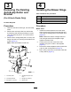
3 4 Removing the Existing Anti-Scalp Roller and Bracket Installing the Blower Hinge Parts needed for this procedure: (For 60-inch Decks Only) No Parts Required Procedure 1 Blower hinge 1 Metal template 3 or 4 Bolt (3/8 x 1 inch) 3 or 4 Locknut (3/8 inch) Procedure 1. Clean the area around the right, rear anti-scalp wheel. 2. Remove the anti-scalp roller from the bracket by loosening and removing the flange nut (3/8 inch) and axle bolt (3/8 x 4-1/2 inch) as shown in Figure 3. 3.
Note: Make sure that the carriage bolts and nuts are tight and that the template is tight against the mower deck. 2. Center punch the new mower deck hole locations using the 3 holes in the template (Figure 6). 3. Remove the metal template and drill 3 pilot holes (1/8 inch) with a sharp drill bit (Figure 6). 4. Drill 3 holes (13/32 inch) holes into the pilot holes with a sharp drill bit (Figure 6). g033910 Figure 4 1. Mower deck 2. Drill the 4 holes (13/32 inch) here. 3.
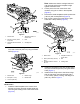
5 Routing the Blower Belt into the Blower Assembly Parts needed for this procedure: 4. Bolt (3/8 x 4-1/2 7. Bushing inch) 2. Bolt (3/8 x 1 inch) 5. Spacer 3. Locknut (3/8 inch) 6. Anti-scalp roller 9. Drilled holes Blower belt 1 Spring Procedure g011056 Figure 7 1. Mower deck 1 1. 8. Blower hinge assembly If present, cut the existing belt cover bracket so that it is flush with the edge of the top deck assembly; refer to Figure 8. Note: Remove any sharp edges.
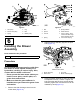
g003398 g002519 Figure 9 Figure 10 1. Idler pulley 4. Peg 1. Bolt 5. Spring installed 2. Mower deck pulley 5. Belt 2. Spacer 6. Grass deflector 3. Spring 6. Blower pulley 3. Locknut 7. L-end of spring; place it behind the deck edge before installing the bolt. 4. Spring 8. J-hook end of spring 6 2. Slide the blower assembly peg into the pivot hole (Figure 11).
g011125 g011127 Figure 12 Model 31213 shown 1. Latch Figure 14 1. Mower deck pulley 3. Blower 2. Spring-loaded Idler pulley 3. Blower assembly 2. Bolt 6. 4. Install the spring as shown in Figure 13. Note: Make sure that the hooks are in the correct position. g011126 Figure 13 1. Spring-loaded idler pulley 3. Long hook end 2. Short hook end 5. Pull the spring-loaded idler pulley back and route the belt around the mower deck pulley.
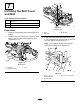
7 Installing the Belt Cover and Bolt Parts needed for this procedure: 1 Belt cover 1 Bolt (1/2 x 2-1/2 inches) 1 Nut (1/2 inch) g011051 Figure 16 Model 31213 Procedure 1. Lower the mower deck to the lowest height-of-cut position. 1. Knob 2. Belt cover 2. Install the new belt cover so the notches on both sides go over the belt cover supports (Figure 15 and Figure 16). 3. 3.
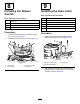
8 9 Installing the Blower Guards Installing the Tube Latch Parts needed for this procedure: Parts needed for this procedure: 1 Front guard 1 Back guard 6 Bolt (1/4 x 5/8 inch) 1 Nut (1/4 inch) Procedure 1. 2. 1 Latch bracket assembly 2 Bolt (3/8 x 2-1/2 inches) 2 Nut (3/8 inch) 1 Latch bracket strap 2 Screw (#10 x 1/2 inch) 2 Nut (#10) Procedure Install the front guard using 3 bolts and a nut (1/4 inch); refer Figure 18. 1. Install the back guard using 3 bolts (Figure 18).
10 Installing the New Belt Cover Bracket Upon Removal of the Kit (For Model 31212 Only) g033957 Figure 20 1. Screw (#10 x 1/2 inch) Parts needed for this procedure: 3. Nut (#10) 2. Latch-bracket strap 1 Belt cover bracket 2 Carriage bolt (1/4 x 3/4 inch) 2 Locknut (1/4 inch) Procedure 1. Drill 2 holes (0.266 inch or drill size H) into the top deck assembly with a sharp drill bit; refer to Figure 21 for the correct positioning. g033989 Figure 21 1. 9.5 cm (3.75 inches) 3. 1.9 cm (0.
g033987 Figure 22 1. Locknut (1/4 inch) 3. New belt cover bracket 2. Drilled hole 4. Carriage bolt (1/4 x 3/4 inch) g012500 Figure 23 1. Throttle stop 11 2. Insert the throttle stop onto the governor shaft so the tab rests against the flat on the speed-control lever (Figure 23). 3. Install the washer and nut onto the shaft and torque to 9.7 to 12.0 N∙m (86 to 106 ft-lb).
Notes:
Notes:
California Proposition 65 Warning Information What is this warning? You may see a product for sale that has a warning label like the following: WARNING: Cancer and Reproductive Harm—www.p65Warnings.ca.gov. What is Prop 65? Prop 65 applies to any company operating in California, selling products in California, or manufacturing products that may be sold in or brought into California.
The Toro Warranty Two-Year or 1,500 Hours Limited Warranty Conditions and Products Covered Parts The Toro Company and its affiliate, Toro Warranty Company, pursuant to an agreement between them, jointly warrant your Toro Commercial product (“Product”) to be free from defects in materials or workmanship for 2 years or 1,500 operational hours*, whichever occurs first. This warranty is applicable to all products with the exception of Aerators (refer to separate warranty statements for these products).