
Operator's Manual


Setup
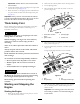
LooseParts
Usethechartbelowtoverifythatallpartshavebeenshipped.
ProcedureDescription
Qty.
Use
Driveshaft
1
Screw,5/16x1–3/4inch
4
Locknut,5/16inch
4
1
Rollpin,3/16x1–1/2inch
2
Installthedriveshafttoaoptionaldeck
orQAS
Retainerpin2
Greasetting
2
2
Washerheadscrew,5/16x7/8inch
2
Usetoinstalloptionalmowerdeck
3
Nopartsrequired
–
AdjusttheROPS
4
Nopartsrequired
–
Checkthetirepressure.
5
Nopartsrequired
–
Checkthehydraulicuid,engineoil,
andcoolantlevels.
MediaandAdditionalParts
Description
Qty.
Use
Operator'sManual
1
Readbeforeoperatingthemachine
EngineOperator'sManual
1
Readbeforeoperatingthemachine
PartsCatalog
1
Usereferencepartnumbers
OperatorTrainingMaterial
1
Viewthevideobeforeoperatingthemachine
1
InstallingtheDriveShafttoan
OptionalMowerDeckorQAS
Partsneededforthisprocedure:
1
Driveshaft
4
Screw,5/16x1–3/4inch
4
Locknut,5/16inch
2
Rollpin,3/16x1–1/2inch
Procedure
Note:PTOdriveshaftinstallationiseasierifthemachineis
positionedonahoist.
1.Parkmachineonalevelsurface,stopengine,engage
parkingbrakeandremovekeyfromtheignitionswitch.
WARNING
Donotstarttheengineandengagethe
PTOswitchwhenthePTOdriveshaftis
disconnectedfromthecuttingdeck.Ifthe
engineisstartedandthePTOshaftisallowed
torotate,seriouspersonalinjuryandmachine
damagecouldresult.BeforethePTOdrive
shaftisdisconnectedfromthecuttingdeck,
disconnectPTOsolenoidcoilconnector
fromwireharnesstopreventunintentional
engagementofthePTOclutch.
2.TopreventtheunintentionalengagementofthePTO
clutch,disconnectthewireharnesselectricalconnector
fromthePTOsolenoidvalvecoilconnector(Figure3).
11