
Operator's Manual


G018339
1
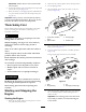
Figure3
1.Wireharnesselectricalconnector
3.PositionthePTOdriveshaftunderthefrontofthe
machine.Makesurethatthedriveshaftslipshaftyoke
(Figure4)istowardthetransmissionPTOshaft.
G018340
1
2
3
4
5
Figure4
1.Transmissiondriveshaft
4.Locknut
2.Capscrew
5.Rollpin
3.PTOshaft
4.Alignthesplineandrollpinholeofdriveshaftyoke
withthetransmissionshaft.
5.SlidePTOdriveshaftendyokeontothetransmission
PTOshaft.
6.SecuretheendyokeofthePTOdriveshaftasfollows:
A.Installtherollpinintheendyokeandshaft.
B.Installthecapscrewsthruthedrivesshaftend
yoke.
C.Installandtightenthelocknutstosecuretheend
yoketothePTOshaft.Torquethelocknutsto20
to25N-m(175to225in-lb).
Note:Retaintheremainingcapscrews,locknuts
androllpintosecuretheotherendofthedrive
shafttotheattachmentgearboxshaft.
7.LubricatethePTOdriveshaftgreasettings.
8.Aftertheotherendofthedriveshaftisconnected
totheattachmentgearboxshaft,connectthewire
harnesselectricalconnectortothePTOsolenoidvalve
coilconnector(Figure3).
2
OptionalMowerDeck
MountingHardware
Partsneededforthisprocedure:
2Retainerpin
2
Greasetting
2
Washerheadscrew,5/16x7/8inch
Procedure
Note:Thesecomponentsandprocedureareonlyrequiredif
amowerdeck,thatrequiresretainerpins,ismountedtothe
tractionunit.RefertotheMowerDeckOperator’sManual
fortheinstallationinstructions
Note:Ifamowerdeckisnottobeinstalledonthetraction
unit,removeortieupthe(4)deckliftchainsfromthelift
suspension.
3
AdjustingtheROPS
NoPartsRequired
Procedure
1.Removethehairpincotterpinsandthepinsfromthe
rollbar(Figure5).
2.Raisetherollbartotheuprightpositionandinstall
thetwopinsandsecurethemwiththehairpincotter
pins(Figure5).
Note:Ifyoumustlowertherollbar,pushthebar
forwardtorelievepressureonthepins,removethe
pins,lowerthebarslowly,andsecureitwiththepinsso
thatitdoesnotdamagethehood.
12