Form No. 3424-897 Rev A Groundsmaster® 360 4-Wheel Drive Multi-Purpose Machine Model No. 31223—Serial No. 403330001 and Up Model No. 31230—Serial No. 403330001 and Up Model No. 31236—Serial No. 403330001 and Up Register at www.Toro.com.
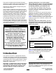
operating instructions or to receive proper training may result in injury. For more information on safe operating practices, including safety tips and training materials, go to www.Toro.com. This product complies with all relevant European directives; for details, please see the separate product specific Declaration of Conformity (DOC) sheet. Genuine Toro spark arresters are approved by the USDA Forestry Service. You may contact Toro directly at www.Toro.
Contents Changing the Engine Oil and Filter.................... 38 Adjusting the Throttle........................................ 39 Fuel System Maintenance ................................... 39 Servicing the Water Separator .......................... 39 Bleeding the Fuel System ................................. 40 Bleeding Air from the Fuel Injectors................... 40 Cleaning the Fuel Tank ..................................... 41 Checking the Fuel Lines and Connections...............................
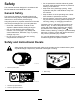
Safety • Do not operate the machine without all guards This machine has been designed in accordance with EN ISO 5395:2013 and ANSI B71.4-2017. • Keep clear of any discharge opening. Keep General Safety • Keep children out of the operating area. Never and other safety protective devices in place and working on the machine. bystanders and pets a safe distance away from the machine. allow children to operate the machine. This product is capable of amputating hands and feet and of throwing objects.
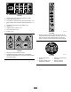
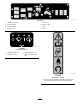
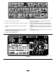
decal117-3233 117-3233 1. Read the Operator's Manual for information on fuses. 2. 4-wheel steer solenoid—7.5 A 3. PTO enable, 4-wheel-steer lamp, deck lift, deck float—7.5 A 4. Glow indicator, fuel-run solenoid, diagnostic light, start—7.5 A 5. Headlights, deck actuator, power takeoff—10 A 6. Lights—15 A 7. Operator-presence switch—10 A 8. Power point, lights—15 A 9. Engine—10 A decal117-3272 117-3272 1.
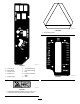
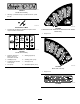
decal120-0250 120-0250 1. Slow-moving vehicle decal117-3277 117-3277 1. Lower decks 6. Two-wheel steering 2. Raise decks 7. Four-wheel steering 3. Engine—stop 8. Fast 4. Engine—run 9. Continuous variable setting 5. Engine—start decal120-0273 120-0273 10. Slow decal117-4766 117-4766 1. Cutting/dismemberment hazard, fan—stay away from moving parts; keep all guards and shields in place.
decal125-7427 125–7427 5. Engine—run 1. Raise/Lower decks 2. 2-wheel steering 6. Engine—start 3. 4-wheel steering 7. Fast 4. Engine—stop 8. Slow decal125-9688 125-9688 Model with Cab Only 1. Windshield wipers—off 3. Windshield wipers—on 2. Windshield wipers 4. Spray windshield washer fluid decal130-0594 130-0594 Model with Cab Only 1. Warning—read the Operator’s Manual; when sitting in the cab, always wear a seat belt; wear hearing protection.
decal130-0611 130-0611 Model with Cab Only 1. Warning—1) Remove the pin; 2) Raise the doors; 3) Exit the cab decaloemmarkt Manufacturer's Mark decal132-6552 132-6552 2-Wheel Drive with ROPS and 4-Wheel Drive with ROPS Models Only 1. Indicates that the blade is identified as a part from the original machine manufacturer. 1. Height of cut decal132-3600 132-3600 Model with Cab Only 1. Read the Operator's Manual for more information on fuses. 2. Headlight (25 A) 5. Working light (20 A) 3.
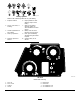
decalbatterysymbols Battery Symbols Some or all of these symbols are on your battery. 1. Explosion hazard 6. Keep bystanders a safe distance away from the battery. 2. No fire, open flame, or smoking 7. Wear eye protection; explosive gases can cause blindness and other injuries. 3. Caustic liquid/chemical burn hazard 4. Wear eye protection. 8. Battery acid can cause blindness or severe burns. 9. Flush eyes immediately with water and get medical help fast. 5. Read the Operator's Manual. 10.
decal117-3273 117-3273 1. Warning—read the Operator's Manual. 6. Thrown object hazard—keep bystanders a safe distance away from the machine. 2. Warning—do not operate this machine unless you are trained. 7. Warning—engage the parking brake, shut off the engine, and remove the key from the key switch before leaving the machine. 3. Warning—wear the seat belt when seated in the operator's 8. Tipping hazard—lower the cutting unit when driving down position.
decal132-3378 132-3378 Model with Cab Only 1. Raise/Lower decks 5. Engine—run 2. 2-wheel steering 6. Engine—start 3. 4-wheel steering 7. Fast 4. Engine—stop 8.
Setup Loose Parts Use the chart below to verify that all parts have been shipped. Procedure Description 1 2 3 4 5 Use Qty. PTO driveshaft Bolt (5/16 x 1-3/4 inches) Locknut (5/16 inch) Roll pin (3/16 x 1-1/2 inches) Retainer pin Grease fitting Washer head screw (5/16 x 7/8 inch) 1 4 4 2 2 2 2 No parts required – Adjust the roll bar. No parts required – Check the tire pressure. No parts required – Check the hydraulic fluid, engine oil, and coolant levels.
D. Torque the locknuts to 20 to 25 N∙m (175 to 225 in-lb). Lubricate the grease fittings on the PTO driveshaft. After you connect the other end of the driveshaft to the attachment gearbox shaft, connect the wire-harness connector to the PTO solenoid-valve-coil connector (Figure 3). 7. 8. 2 g018339 Figure 3 Using the Optional Mower-Deck-Mounting Hardware 1. Wire-harness connector 3. Position the PTO driveshaft under the front of the machine.
Product Overview Controls Become familiar with all the controls before you start the engine and operate the machine. Traction Pedal The traction pedal (Figure 6) controls the forward and reverse operation. Press the top of the pedal to move forward and the bottom to move rearward. The ground speed depends on how far you press the pedal. For no load, maximum ground speed, fully press the pedal while the throttle is in the FAST position. g014166 Figure 5 1. Roll bar 3.
you, press the foot pedal and release it when the steering wheel reaches the desired operating position. Parking Brake To engage the parking brake, push down on the brake pedal and press the top forward to latch it (Figure 6). To disengage the parking brake, press the brake pedal until the parking-brake latch retracts. Key Switch The ignition switch has 3 positions: OFF, ON/PREHEAT , and START (Figure 7). g014170 Figure 8 1. Fuel gauge 2.
Glow-Plug-Indicator Light (Orange Light) The glow-plug-indicator light (Figure 7) turns on when you turn the ignition switch to the ON position. It remains on for 6 seconds. When the light turns off, you can start the engine. Charge-Indicator Light The charge-indicator light illuminates when the charging-system circuit malfunctions (Figure 7). Oil-Pressure Warning Light g014333 Figure 9 The oil-pressure warning light glows if the engine-oil pressure drops below a safe level (Figure 7).
Diagnostic Ace Display Windshield-Wiper Switch The machine comes with an electronic controller which controls most of the machine functions. The controller determines what function is required for various input switches (e.g., seat switch and key switch) and turns on the outputs to actuate solenoids or relays for the requested machine function. Use this switch to turn the wind shield wipers on or off (Figure 10). Air-Conditioning Switch Use this switch to turn the air conditioning on or off (Figure 10).
Specifications Note: Specifications and design are subject to change without notice.
Operation Weight of the Machine with Mower Decks 4-Wheel Drive Machine with ROPS Machine with Cab 2-Wheel Drive Machine with ROPS No mower deck 1,134 kg (2,500 lb) 1,361 kg (3,000 lb) 1,088 kg (2,398 lb) 72 inch side discharge mower deck 1,344 kg (2,964 lb) 1,571 kg (3,464 lb) 1,298 kg (2,862 lb) 72 inch base mower deck 1,323 kg (2,916 lb) 1,549 kg (3,416 lb) 1,276 kg (2,814 lb) 62 inch base mower deck 1,305 kg (2,878 lb) 1,532 kg (3,378 lb) 1,259 kg (2,776 lb) 100 inch rear discharge mo
Adding Fuel Important: The petroleum diesel portion must Fuel Specification Observe the following precautions: • Never use kerosene or gasoline instead of diesel • Biodiesel blends may damage painted surfaces. be ultra-low sulfur. fuel. • Use B5 (biodiesel content of 5%) or lesser blends in cold weather. • Never mix kerosene or used engine oil with the diesel fuel.
Checking the Engine-Oil Level the NEUTRAL position with the parking brake engaged. If you rise from the seat when the PTO is engaged there is a 1-second delay and then the engine shuts off. Before you start the engine and use the machine, check the oil level in the engine crankcase; refer to Checking the Engine-Oil Level (page 37).
To adjust the back of the seat, turn the knob, located under the right-side armrest, in either direction to provide the best comfort (Figure 14). Changing the Lumbar Support You can adjust the back of the seat to provide a customized lumbar support for your lower back. To adjust the back of the seat, turn the knob, under the left-side armrest, in either direction to provide the best comfort (Figure 14).
• Use care when approaching blind corners, shrubs, • • • • g014265 Figure 17 • 1. Seat-latch-release bar • • During Operation During Operation Safety General Safety • The owner/operator can prevent and is responsible for accidents that may cause personal injury or property damage. • • Wear appropriate clothing, including eye protection; long pants; substantial, slip-resistant footwear; and hearing protection. Tie back long hair and do not wear loose jewelry.
• A cab installed by Toro is a roll bar. • Always wear your seat belt. or the edge caves in. Establish a safety area between the machine and any hazard. • Identify hazards at the base of the slope. If there are hazards, mow the slope with a pedestrian-controlled machine. Machines with a Foldable Roll Bar • Always use the seat belt with the roll bar in the • If possible, keep the cutting unit(s) lowered to the raised position. ground while operating on slopes.
g014175 Figure 19 1. Power-takeoff switch (PTO) 3. Glow-plug light 2. Ignition switch 4. Throttle lever 5. Move the throttle lever midway between the FAST and SLOW positions (Figure 19). 6. Turn the ignition key clockwise to the RUN position (Figure 20). g014172 Figure 18 1. Pin 3. Roll bar (raised position) 2. Hairpin 4. Roll bar (lowered position) 3. Raise the roll bar to the upright position (Figure 18). 4. Secure the roll bar with the 2 pins and 2 hairpins (Figure 18).
8. Leave the throttle midway between the SLOW and FAST positions until the engine and the hydraulic system warm up. Engage the parking brake whenever you leave the machine and remove the key. Important: When you start the engine for Selecting the Steering Mode the first time, change the engine oil, or overhaul the engine, transmission, or wheel motor, operate the machine with the throttle lever in the SLOW position in both the forward and reverse directions for 1 to 2 minutes.
Engaging the Power Takeoff (PTO) green light stops flashing and remains off. When the switch light is continuously off, the machine is in the 4-wheel-steering mode. The power-takeoff (PTO) switch starts and stops the mower blades and some powered attachments. 1. If the engine is cold, allow the engine to warm up 5 to 10 minutes before engaging the PTO. 2. While seated in the seat, ensure that the traction pedal is in the NEUTRAL position and that the engine is at full throttle. 3.
Select the Proper Height-of-Cut Setting to Suit Conditions The third row down gives you the height listed plus 12 mm (1/2 inch). The bottom row gives you the height listed plus 18 mm (3/4 inch). For the 15.8 cm (6 inches) position, there is only 1 hole, located in the second row. This does not add 6 mm (1/4 inch) to the 15.8 cm (6 inches) position. Remove approximately 25 mm (1 inch) or no more than 1/3 of the grass blade when cutting.
Changing to Machine Operation After Operation 1. After Operation Safety Rotate each bypass valve clockwise 1 turn and hand tighten them (Figure 25). Note: Do not overtighten the bypass valves. • Clean grass and debris from the cutting units, 2. mufflers, and engine compartment to help prevent fires. Clean up oil or fuel spills. • If the cutting units are in the transport position, use Torque the valves approximately 8 N∙m (71 in-lb) as shown in Figure 25.
Locating the Tie-Down Points There are tie downs located at the front and rear sides of the machine (Figure 26). Note: Use properly-rated DOT-approved straps in 4 corners to tie down the machine. • 2 on the front of the operator's platform • Rear tire g014264 Figure 26 1. Front tie-down point 2.
Maintenance Note: Determine the left and right sides of the machine from the normal operating position. Download a free copy of the electrical or hydraulic schematic by visiting www.Toro.com and searching for your machine from the Manuals link on the home page. Maintenance Safety – Allow machine components to cool before performing maintenance.
Maintenance Service Interval Maintenance Procedure Every 400 hours • Service the air cleaner. (Service the air cleaner earlier if the air-cleaner indicator shows red. Service it more frequently in extremely dirty or dusty conditions.) • Replace the fuel-filter canister. • Check the fuel lines and connections. Every 800 hours • Change the hydraulic fluid and filter. • Inspect the engine-valve clearance. Refer to your engine owner's manual. Every 1,500 hours Every 2 years • Replace any moving hoses.
Daily Maintenance Checklist Duplicate this page for routine use. For the week of: Maintenance Check Item Monday Tuesday Wednesday Thursday Friday Saturday Check the safety-interlock operation. Check the brake operation. Check the engine-oil level. Check the cooling-system-fluid level. Drain the water/fuel separator. Check the air filter, dust cup, and burp valve. Check for unusual engine noises.2 Check the radiator and screen for debris Check for unusual operating noises.
Notation for Areas of Concern Inspection performed by: Item Date Information Pre-Maintenance Procedures CAUTION If you leave the key in the key switch, someone could accidently start the engine and seriously injure you or other bystanders. Remove the key from the key switch before you do any maintenance. g015806 Figure 27 Preparing the Machine for Maintenance 1. Ensure that the PTO is disengaged. 2. Park the machine on a level surface. 3. Engage the parking brake. 4.
Lubrication The machine has grease fittings that you must lubricate regularly with No. 2 lithium grease. Lubricate the grease fittings immediately after every washing, regardless of interval specified. Greasing the Bearings and Bushings Service Interval: Every 50 hours Grease the bearing and bushing grease fittings more frequently in extremely dusty and dirty conditions. 1. Wipe the grease fittings clean so that foreign matter cannot be forced into the bearing or bushing (Figure 29). 2.
Note: To access the grease fittings for the rear-steering linkage, remove the storage compartment. migration through both the upper and lower king-pin bushings. You should see grease purging out of both the top and the bottom of the axle casting/bushing assembly areas of all 4 kingpin assemblies (Figure 30).
Engine Maintenance Note: This cleaning process prevents debris Engine Safety 3. • Shut off the engine before checking the oil or adding oil to the crankcase. • Do not change the governor speed or overspeed the engine. Servicing the Air Cleaner Service Interval: Every 400 hours 4. Check the air-cleaner body for damage that could cause an air leak. Replace a damaged air cleaner. Check the whole intake system for leaks, damage, or loose hose clamps. 5. 6.
Changing the Engine Oil and Filter If the engine oil level is above the Full mark, change the engine oil. The best time to check the engine oil is when the engine is cool before it has been started for the day. If it has already been run, allow the oil to drain back down to the sump for at least 10 minutes before checking. If the oil level is at or below the Add mark on the dipstick, add oil to bring the oil level to the Full mark. Do not overfill the engine with oil.
Adjusting the Throttle 1. 2. Fuel System Maintenance Move the throttle lever forward to the front of the control panel slot and then move it back approximately 3 mm (1/8 inch) into the FAST idle position. Note: Refer to Fuel Specification (page 20) for the proper fuel recommendations. Check the position of the speed control lever on the fuel-injection pump. The speed-control lever should contact the high-speed screw when the throttle-control lever is in the FAST (detent) position (Figure 33).
g003993 Figure 35 1. Bleed screw 4. Turn the key in the ignition switch to the ON position. The electric fuel pump will begin operation, thereby forcing air out around the air bleed screw. Leave the key in the ON position until a solid stream of fuel flows out around the screw. 5. Tighten the screw and turn the key to the OFF position. Note: The engine should start after you perform this procedure.
Electrical System Maintenance Electrical System Safety • Disconnect the battery before repairing the machine. Disconnect the negative terminal first and the positive last. Connect the positive terminal first and the negative last. • Charge the battery in an open, well-ventilated area, away from sparks and flames. Unplug the charger before connecting or disconnecting the battery. Wear protective clothing and use insulated tools. g003973 Figure 36 1. Fuel injectors 2.
WARNING Incorrect battery cable routing could damage the machine and cables causing sparks. Sparks can cause the battery gasses to explode, resulting in personal injury. • Always disconnect the negative (black) battery cable before disconnecting the positive (red) cable. g028467 Figure 38 • Always connect the positive (red) battery cable before connecting the negative (black) cable. 1. Cover 2.
CAUTION If safety interlock switches are disconnected or damaged, the machine could operate unexpectedly, causing personal injury. • Do not tamper with the interlock switches. • Check the operation of the interlock switches daily and replace any damaged switches before operating the machine. Verifying the Interlock Switch Function 1. g004140 Figure 40 Park the machine on a level surface, lower the attachment, shut off the engine, and engage the parking brake. 2. Raise the seat. 3.
Verifying the Output Function 1. Park the machine on a level surface, lower the attachment, shut off the engine, and engage the parking brake. 2. Raise the seat. 3. Locate wire harness and connectors near the controller. 4. Carefully unplug the loopback connector from the harness connector. 5. Connect the Diagnostic ACE connector to the appropriate harness connector. If the machine comes with a front attachment, it will have 2 controllers. everyday use of the machine.
Drive System Maintenance 2. On a paved or dirt surface, turn the steering wheel to the left or right and continue turning until all 4 wheels have stopped turning. Automatic synchronization of the wheel alignment should occur. Checking the Tire Pressure Important: Doing this procedure on turf can Service Interval: Every 50 hours result in turf damage directly under each of the turning tires. Maintain the air pressure in the front and rear tires.
Cooling System Maintenance 3. Install the expansion-tank cap. Cooling System Safety • Swallowing engine coolant can cause poisoning; keep out of reach from children and pets. • Discharge of hot, pressurized coolant or touching a hot radiator and surrounding parts can cause severe burns. – Always allow the engine to cool at least 15 minutes before removing the radiator cap. – Use a rag when opening the radiator cap, and open the cap slowly to allow steam to escape.
step from the front of the radiator, again from the fan side. Brake Maintenance 4. After you have thoroughly cleaned the radiator, remove any debris from the channel at the radiator base and around the frame. Adjusting the Brakes 5. Clean the engine compartment and the brake linkage. 6. Close the clean-out cover and secure the flange nut. 7. Close the hood.
Belt Maintenance Checking the Alternator Belt Service Interval: Every 100 hours After the first 10 hours 1. Open the hood and secure the prop rod. 2. Check the tension of the alternator belt by pressing it (Figure 47) midway between the alternator and the crankshaft pulleys with 10 kg (22 lb) of force. g011617 Figure 46 1. Brake cables 3. Parking-brake pawl 2. Screws (2) 4. Brake detent 2.
Controls System Maintenance Adjusting the Traction Drive for Neutral Note: If the machine has recently had the hydraulic fluid changed or the traction motors or hoses replaced, work out any air trapped in the system prior to performing this procedure. To do this, operate the machine in forward and reverse for a few minutes and then replenish the oil as required. Note: When positioned on a level surface, the machine must not creep when you release the traction pedal. 1. 2.
Hydraulic System Maintenance for all moving parts to stop before leaving the operating position. 3. Loosen the jam nut on the stop bolt for the traction pedal (Figure 49). Hydraulic System Safety • Seek immediate medical attention if fluid is injected into skin. Injected fluid must be surgically removed within a few hours by a doctor. Ensure that all hydraulic-fluid hoses and lines are in good condition and all hydraulic connections and fittings are tight before applying pressure to the hydraulic system.
Important: Do not engage the PTO. 3. 3. Raise the deck to extend the lift cylinders, shut off the engine, and remove the key. 4. Remove the hydraulic-filler cap (Figure 50) from the filler neck. 5. Remove the dipstick and wipe it with a clean rag (Figure 50). 6. Screw the dipstick all the way into the filler neck; then remove it, and check the level of the fluid (Figure 50).
Cab Maintenance Cleaning the Cab Important: Use care around the cab seals and lights (Figure 52). If you are using a pressure washer, keep the washer wand at least 0.6 m (2 ft) away from the machine. Do not use the pressure washer directly on the cab seals and lights or under the rear overhang. g028438 Figure 53 Washer-Fluid Bottle with Washer-Fluid Symbol 3. Fill the bottle with washer fluid as needed. 4. Close the hood. Cleaning the Cab Air Filters Service Interval: Every 250 hours 1.
Cleaning the Air-Conditioning Coil Service Interval: Every 50 hours Clean the air-conditioning coil more frequently in extremely dusty or dirty conditions. 1. Perform the pre-maintenance procedure; refer to Preparing the Machine for Maintenance (page 34). 2. Lift the 4 tabs on the air-conditioning screen (Figure 56) and remove the screen from the top of the cab. g028379 Figure 55 Rear Cab Air Filter 1. Filter 2. Grate 2. 3.
5. Cleaning Clean the screen, air-conditioning duct, fans, and fan panel using low-pressure air no greater than 276 kPa (40 psi). Waste Disposal Important: Do not use water to clean the condenser because moisture on the components attracts dirt and dust, which make the components more difficult to clean. 6. Install the fan-panel assembly and fans to the underside of the cab top with the 2 knobs that you loosened and removed in step 4. 7.
Storage B. Clean the battery, terminals, and posts with a wire brush and baking-soda solution. Preparing the Engine C. Coat the cable terminals and battery posts with Grafo 112X skin-over grease (Toro Part No. 505-47) or petroleum jelly to prevent corrosion. D. Slowly charge the battery for 24 hours every 60 days to prevent lead sulfation of the battery. 1. Drain the engine oil from the oil pan and install the drain plug. 2.
Notes:
Notes:
EEA/UK Privacy Notice Toro’s Use of Your Personal Information The Toro Company (“Toro”) respects your privacy. When you purchase our products, we may collect certain personal information about you, either directly from you or through your local Toro company or dealer.
California Proposition 65 Warning Information What is this warning? You may see a product for sale that has a warning label like the following: WARNING: Cancer and Reproductive Harm—www.p65Warnings.ca.gov. What is Prop 65? Prop 65 applies to any company operating in California, selling products in California, or manufacturing products that may be sold in or brought into California.
The Toro Warranty A Two-Year Limited Warranty Conditions and Products Covered The Toro Company and its affiliate, Toro Warranty Company, pursuant to an agreement between them, jointly warrant your Toro Commercial product (“Product”) to be free from defects in materials or workmanship for two years or 1500 operational hours*, whichever occurs first. This warranty is applicable to all products with the exception of Aerators (refer to separate warranty statements for these products).