
Operator's Manual


Table Of Contents
- NO TITLE
- .
- NO TITLE
- NO TITLE
- NO TITLE
- NO TITLE
- NO TITLE
- NO TITLE
- What is this warning?
- What is Prop 65?
- Does this law apply everywhere?
- How do the California warnings compare to federal limits?
- Why don’t all similar products carry the warning?
- Why does Toro include this warning?
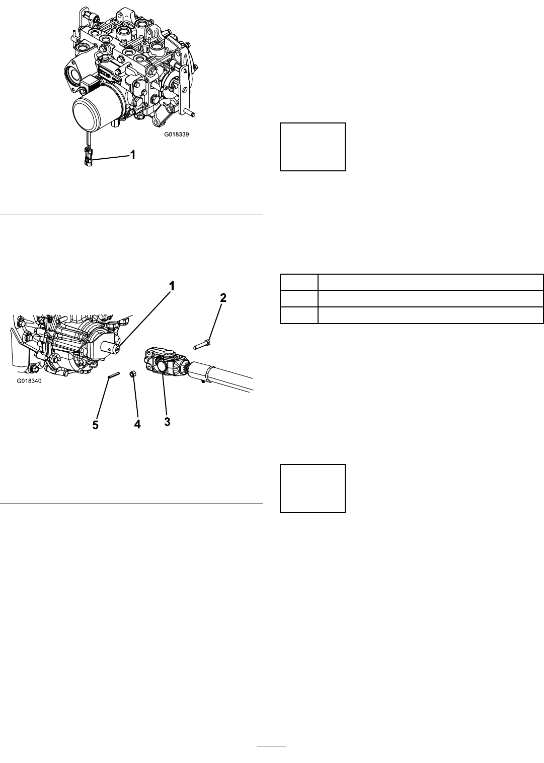
g018339
Figure3
1.Wire-harnessconnector
3.PositionthePTOdriveshaftunderthefrontofthe
machine.Ensurethattheslip-shaftyokeofthe
driveshaftispositionedtowardthetransmission
driveshaft(Figure4).
g018340
Figure4
1.Transmissiondriveshaft
4.Locknut
2.Bolt5.Rollpin
3.PTOdriveshaft
4.Alignthesplineandroll-pinholeofthedriveshaft
yokewiththetransmissiondriveshaft.
5.SlidethePTOdriveshaftendyokeontothe
transmissiondriveshaft.
6.SecuretheendyokeofthePTOdriveshaftas
follows:
A.Installtherollpinintheendyokeandshaft.
B.Installtheboltsthroughthedriveshaftend
yoke.
C.Installandtightenthelocknutstosecurethe
endyoketothePTOdriveshaft.
Note:Retaintheremainingbolts,locknuts,
androllpintosecuretheotherendofthe
driveshafttotheattachmentgearboxshaft.
D.Torquethelocknutsto20to25N∙m(175
to225in-lb).
7.LubricatethegreasettingsonthePTO
driveshaft.
8.Afteryouconnecttheotherendofthedriveshaft
totheattachmentgearboxshaft,connect
thewire-harnessconnectortothePTO
solenoid-valve-coilconnector(Figure3).
2
UsingtheOptional
Mower-Deck-Mounting
Hardware
Partsneededforthisprocedure:
2Retainerpin
2
Greasetting
2
Washerheadscrew(5/16x7/8inch)
Procedure
Note:Thesecomponentsandprocedurearerequired
onlyifamowerdeckthatrequiresretainerpinsis
mountedtothetractionunit.Refertothemowerdeck
Operator’sManualfortheinstallationinstructions.
Note:Ifyouarenotinstallingamowerdeckonthe
tractionunit,removeortieupthe4deck-liftchains
fromtheliftsuspension.
3
AdjustingtheRollBar
NoPartsRequired
Procedure
1.Removethe2hairpinsandthe2pinsfromthe
rollbar(Figure5).
2.Raisetherollbartotheuprightpositionand
secureitwiththe2pinsand2hairpins(Figure
5).
Note:Ifyoumustlowertherollbar,pushthebar
forwardtorelievepressureonthepins,remove
thepins,lowerthebarslowly,andsecureitwith
thepinssothatitdoesnotdamagethehood.
13