
Service Manual


Rev. A
Groundsmaster 360Hydraulic System Page 4 − 134
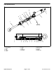
Deck Lift Manifold
1. Steering control manifold
2. Flat washer (2)
3. Cap screw (2)
4. AWD control manifold
5. O−ring
6. 90
o
hydraulic fitting
7. O−ring (7)
8. O−ring
9. Straight hydraulic fitting
10. Deck lift manifold
11. Flange nut (2)
12. Hydraulic adapter
13. O−ring
14. Mount plate
15. Mount (2)
16. Flange nut (2)
17. Cap screw (2)
Figure 148
4
5
7
8
11
1
12
13
3
2
6
9
10
14
7
7
15
16
17
FRONT
RIGHT
SHOWN
SERIAL NUMBER
BELOW 313999999
NOTE: On machines with serial number below
313999999, the deck lift manifold mount plate is se-
cured to the frame (Fig. 148). The mount plate is a frame
component on machines with serial number above
314000000 (Fig. 149). The following procedure can be
used for all Groundsmaster 360 machines.
Deck Lift Manifold Removal (Fig. 148 or 149)
WARNING
Before disconnecting or performing any work o
n
the hydraulic system, all pressure in the system
must be relieved. See Relieving Hydraulic System
Pressure in the General Information section.
1. Park machine on a level surface, lower cutting deck,
stop engine, engage parking brake and remove key
from the ignition switch.
2. Raise and support operator seat to access deck lift
manifold.
WARNING
Make sure that cutting deck is fully lowered and
supported before loosening hydraulic lines, car-
tridge valves or plugs from lift manifold. If deck is
raised as manifold components are loosened,
deck may drop unexpectedly.