
Service Manual


Groundsmaster 360 Page 5 − 47 Electrical System
(Rev. A)
Hydraulic Solenoid Valve Coils
The Groundsmaster 360 hydraulic control manifolds
use several hydraulic solenoid valve coils for system
control. The deck lift manifold includes two (2) solenoid
valves and the steering control manifold on 4WD ma-
chines includes a single solenoid valve. When the sole-
noid coils are energized, hydraulic valve shift occurs to
control hydraulic circuit flow. Testing of the coils can be
done with the coil installed on the hydraulic valve.
Testing
NOTE: Before disconnecting solenoid valve coils on
machines with 4WD, test the solenoids and their circuit
wiring as TEC controller outputs with the Diagnostic Dis-
play (see Diagnostic Display in the Troubleshooting sec-
tion of this chapter). The Diagnostic Display will identify
if the TEC output to the solenoid coil exists when ma-
chine controls are in the correct position. If the TEC out-
put exists for a solenoid coil but the coil is not functioning
correctly, suspect a failed coil or an open in the solenoid
valve coil circuit.
1. Park machine on level surface, lower cutting deck,
stop engine, apply parking brake and remove key from
ignition switch. To gain access to control manifolds and
solenoid coils, raise and support the operator seat.
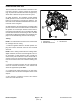
2. Disconnect harness electrical connector from hy-
draulic solenoid valve coil that is to be tested (Fig. 60).
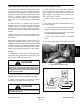
3. Identify coil resistance specification by measuring
the coil diameter and coil height (Fig. 61).
NOTE: Prior to taking small resistance readings with a
digital multimeter, short the meter test leads together.
The meter may display a small resistance value (usually
0.5 ohms or less). This resistance is due to the internal
resistance of the meter and test leads. Subtract this val-
ue from the measured value of the solenoid coil being
testing.
NOTE: Solenoid coil resistance should be measured
with solenoid at approximately 68
o
F (20
o
C). Resistance
may be slightly different than listed at different tempera-
tures. Typically, a failed solenoid coil will either be
shorted (very low or no resistance) or open (infinite re-
sistance).
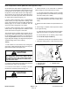
4. Using a multimeter (ohms setting), measure resis-
tance between the two (2) connector terminals on the
solenoid valve coil. The resistance for the solenoid coils
is identified in Figure 62.
5. If solenoid coil resistance is incorrect, replace sole-
noid (see Hydraulic Solenoid Valve Coil Removal and
Installation in the Service and Repairs section of this
chapter).
NOTE: On machines with a serial number below
315000000, the two (2) solenoid valve coils on the deck
lift manifold are identical. To assist in troubleshooting,
identical coils can be exchanged. If the problem follows
the exchanged coil, an electrical problem likely exists
with the coil. If the problem remains unchanged, some-
thing other than the solenoid coil is the problem source
(e.g. switch, circuit wiring, hydraulic problem).
6. After coil testing is completed, connect wire harness
electrical connector to the solenoid valve coil. Lower
and secure seat.
1. Lift manifold
2. Steering manifold
3. Transmission
Figure 60
X
Y
Z
1
3
2
x
Figure 61
COIL
DIAMETER
COIL
HEIGHT
COIL
DIAMETER
COIL
HEIGHT
COIL
RESISTANCE
1.84 in
(46.7 mm)
1.96 in
(49.9 mm)
7.1 ohm
1.41 in
(35.8 mm)
1.43 in
(36.3 mm)
8.8 ohm
Figure 62
Electrical
System