
Service Manual


Rev. A
Groundsmaster 360 Page 6 − 5 Chassis
Steering Stop Adjustment
Proper adjustment of the steering stop bolts is neces-
sary to allow full rotation of the wheels when steering
your Groundsmaster 360.
1. Park machine on a level surface, lower cutting deck
and engage parking brake. Make sure that the PTO
switch is OFF.
2. Lubricate all grease fittings in front and rear steering
assemblies.
3. Move the steering selector switch to the 2 wheel
steer position which will allow the steering stops to be
checked on the front axle.
A. Rotate the steering wheel so that the front tires
are fully turned in one direction. The front steering
cylinder should extend or retract fully and the effort to
turn the steering wheel should be consistent as the
tires move to the fully turned position.
B. If turning the steering wheel gets difficult as the
tires turn fully and there is evidence that the steering
system relief valve is opening, the cap screw on the
front axle that acts as the stop needs to be adjusted.
C. Loosen jam nut on the stop screw and adjust stop
screw until system is no longer going over relief at full
tire rotation. At the end of the steering cylinder
stroke, the cylinder re−phasing check valve should
allow the cylinder to stay extended without excessive
circuit pressure.
D. Turn the stop screw into the axle 1/2 turn and then
tighten the jam nut. When the stop screw is properly
adjusted, there should be a very small gap between
the stop screw and the steering fork when the tires
are fully turned in one direction.
E. Repeat the above steps for the other direction of
front wheel turning.
4. After the front axle stops are adjusted, move the
steering selector switch to the 4 wheel steer position
which will allow the steering stops to be checked on the
rear axle. Follow the steps above to check and adjust the
stops on the rear axle.
NOTE: If steering stops can not be adjusted using the
above procedure, check that wheel alignment is correct-
ly adjusted (see Wheel Alignment in this section). Also,
carefully inspect all steering system components for
wear or damage.
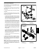
1. Front axle
2. Steering cylinder
3. Jam nut (2)
4. Stop screw (2)
Figure 5
3
2
4
1
SHOWN
SERIAL NUMBER
BELOW 314999999
FRONT
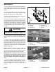
1. Rear axle
2. Steering cylinder
3. Jam nut (2)
4. Stop screw (2)
Figure 6
1
4
3
2
SHOWN
SERIAL NUMBER
BELOW 314999999
FRONT
Chassis