
Service Manual


Rev. A
Groundsmaster 360 Page 6 − 27 Chassis
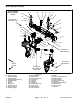
NOTE: The front axle steering cylinder on machines
with serial numbers above 315000000 is installed in the
reverse direction of machines with lower serial num-
bers. Figure 30 shows the cylinder orientation for ma-
chines with the higher serial number. Use the following
procedure and torque specifications identified in Figure
29 when servicing the front axle on all Groundsmaster
360 machines.
Disassembly (Fig. 29)
1. Park machine on a level surface, lower cutting deck,
stop engine and remove key from the ignition switch.
2. Remove front cover from front axle to allow access
to front steering components (Fig. 31).
3. Remove front wheel if necessary (see Wheel Re-
moval in this section).
4. Remove steering cylinder if necessary (see Steering
Cylinder Removal in the Service and Repairs section of
Chapter 4 − Hydraulic System).
5. On 2WD machines, remove front spindle if neces-
sary (see Front Spindle Removal in this section).
6. On 4WD machines, remove front wheel motor if nec-
essary (see Wheel Motor Removal in the Service and
Repairs section of Chapter 4 − Hydraulic System).
7. Remove front steering fork assembly if necessary
(see Front Steering Fork Removal in this section).
8. To remove tie rod (item 34) from machine:
A. Remove cotter pin and slotted hex nut that secure
outer tie rod ball joint stud to steering fork.
B. Separate ball joint from steering fork.
C. Unscrew inner tie rod end from center link and re-
move tie rod from machine.
NOTE: Inner and outer tie rod ends are not available
separately. If wear or damage occurs to tie rod compo-
nents, replace tie rod assembly.
9. Remove additional front steering components as
necessary using Figure 29 as a guide.
10.If bushings in the front axle (item 5 or 6 in Fig. 31),
front axle LH arm (item 29 in Fig. 29) or front axle RH arm
(item 32 in Fig. 29) are worn or damaged, replace bush-
ings (see Steering Assembly Bushing Service in this
section).
1. Front axle
2. Steering cylinder
3. Front axle RH arm
4. Front axle LH arm
5. Front pin (2)
6. Center link
Figure 30
1
3
4
2
6
5
SHOWN
SERIAL NUMBER
ABOVE 315000000
FRONT
RIGHT
1. Front cover
2. Screw (2)
3. Flat washer (2)
4. Grommet (2)
5. Tinnerman nut (2)
6. Front axle
Figure 31
FRONT
RIGHT
1
3
4
2
5
6
Chassis