
Service Manual


Rev. A
Groundsmaster 360Page 6 − 28Chassis
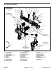
Assembly (Fig. 29)
1. Install all removed front steering components using
Figure 29 as a guide. Note torque specifications identi-
fied in Figure 29 during assembly. If front axle was re-
moved from frame, use washers (item 37) so axle has
less than 0.030” (0.76 mm) free play between frame and
axle support. If ball joints were removed from center link
(item 26), press new ball joints into center link from the
side of the link that has a notch at ball joint bore (Fig. 33).
2. To install tie rod (item 34) to vehicle:
A. If tie rod assembly is being replaced, adjust new
tie rod assembly to approximate length of removed
tie rod.
B. Apply Loctite #271 (or equivalent) to threads of
inner tie rod end. Thread tie rod into center link and
torque from 70 to 80 ft−lb (95 to 108 N−m).
C. Clean tapers of steering fork and outer tie rod end
ball joint stud.
D. Insert outer tie rod end ball joint stud into steering
fork and secure with slotted hex nut. Torque slotted
hex nut from 35 to 40 ft−lb (48 to 54 N−m). If neces-
sary, tighten nut further until slot in nut aligns with
hole in tie rod ball joint stud. Install cotter pin.
3. If steering cylinder was removed, install cylinder (see
Steering Cylinder Installation in the Service and Repairs
section of Chapter 4 − Hydraulic System).
4. If front steering fork assembly was removed, install
steering fork (see Front Steering Fork Installation in this
section).
5. If front spindle on 2WD machine was removed,
install front spindle (see Front Spindle Installation in this
section).
6. If front wheel motor on 4WD machines was removed,
install wheel motor (see Wheel Motor Installation in the
Service and Repairs section of Chapter 4 − Hydraulic
System).
7. If front wheel was removed, install wheel (see Wheel
Installation in this section).
8. Install front cover to front axle (Fig. 31).
Failure to maintain proper wheel lug nut torque
could result in failure or loss of wheel and may re
-
sult in personal injury.
WARNING
9. If front wheel was removed, make sure that lug nuts
are torqued evenly in a crossing pattern from 75 to 85
ft−lb (102 to 115 N−m).
10.Lubricate all grease fittings in front steering assem-
bly.
11.Check and adjust wheel alignment (see Wheel Align-
ment in the Adjustments section of this chapter).
1. Dust cover
2. Outer tie rod end
3. Jam nut
4. Inner tie rod end
Figure 32
3
4
2
1
1. Center link
2. Ball joint (2)
3. Center link notch
4. Retaining ring (2)
Figure 33
1
3
2
4
FRONT