
Service Manual


Groundsmaster 360Page 7 − 14Cutting Deck
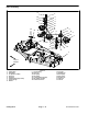
Gearbox
1. Flange nut (3)
2. Washer (3)
3. LH gearbox bracket
4. Mount (3)
5. Carriage screw (3)
6. Gearbox
7. Grommet (5)
8. Taper−lock bushing
9. RH gearbox bracket
10. Cap screw (4)
11. Lock washer (4)
12. Woodruff key
13. Deck drive pulley
14. RH deck cover
15. LH deck cover
16. Knob (2)
17. Set screw (2)
18. Retainer nut (2)
Figure 15
FRONT
RIGHT
2
7
3
4
5
1
9
6
8
10
11
12
13
14
15
16
7
18
17
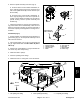
Removal (Fig. 15)
1. Park machine on a level surface, lower cutting deck,
stop engine, engage parking brake and remove key
from the ignition switch.
2. Lift the footrest, exposing the top of the cutting deck.
Support the footrest with prop rod.
3. Remove belt covers from top of cutting deck.
4. Remove drive belt from deck pulleys.
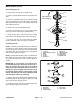
WARNING
Do not start the engine and engage the PTO
switch when the PTO drive shaft is disconnected
from the cutting deck. If the engine is started and
the PTO shaft is allowed to rotate, serious per-
sonal injury and machine damage could result. If
the PTO drive shaft is disconnected from the cut-
ting deck, disconnect PTO solenoid coil connec-
tor from wire harness to prevent unintentional
engagement of the PTO clutch.