
Service Manual


Groundsmaster 360Page 3 − 14Kubota Diesel Engine
Engine
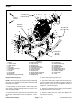
Figure 9
1. Engine
2. Thermo−switch
3. Cable support
4. Fan
5. Fan pulley
6. Flange head screw (4)
7. Fan spacer
8. Hex nut
9. Lock washer
10. Flat washer
11. Engine mount (2) (yellow top)
12. Motor mount plate (2)
13. Cap screw (2)
14. Flange nut (2)
15. Snubbing washer (2)
16. Cap screw (4 per plate)
17. Lock washer (10)
18. Flange screw (4)
19. Flange nut (6)
20. Engine mount (2) (red top)
21. Flange head screw (4)
22. Flange nut (4)
23. Cap screw (2)
24. Hardened washer (2)
25. Flat washer (2)
26. Flywheel housing
27. Dowel pin (2)
28. Flange head screw (6)
29. Socket head screw (2)
30. Flywheel coupling
31. Cap screw (6)
32. V−belt
34 to 42 ft−lb
(47 to 56 N−m)
19 ft−lb
(26 N−m)
Loctite #271
FRONT
RIGHT
7
6
17
33
1
2
3
5
8910
11
12
13
14
15
16
17
18
19
20
21
22
23
24
25
26
27
28
29
30
31
4
19
32
70 to 86 in−lb
(7.9 to 9.7 N−m)
Antiseize
Lubricant
Engine Removal (Fig. 9)
NOTE: When removing the engine using the following
procedure, the flywheel housing and transmission will
remain in the machine.
1. Park machine on a level surface, lower cutting unit,
stop engine, engage parking brake and remove key
from the ignition switch.
2. Remove hood from machine (see Hood Removal in
the Service and Repairs section of Chapter 6 − Chas-
sis).
3. Raise and support operator seat.
4. Disconnect both battery cables from the battery. Dis-
connect negative cable first and then positive cable (see
Battery Service in the Service and Repairs section of
Chapter 5 − Electrical System).
5. Remove air cleaner from the engine (see Air Cleaner
Assembly Removal in this section).
6. Remove muffler from the engine (see Muffler Re-
moval in this section).