
Service Manual


Groundsmaster 360 Hydraulic SystemPage 4 − 53
The Gear Pump Flow Test should be performed if a
steering or cutting deck raise and lower problem is iden-
tified. This test will determine if hydraulic flow from the
gear pump is correct.
Procedure for Gear Pump Flow
Test:
NOTE: Over a period of time, the gears and wear plates
in the gear pump can wear. A worn pump will bypass oil
and make the pump less efficient. Eventually, enough oil
loss will occur to cause the cutting unit motors to stall un-
der heavy cutting conditions. Continued operation with
a worn, inefficient pump can generate excessive heat
and cause damage to seals and other components in
the hydraulic system.
1. Make sure hydraulic oil is at normal operating tem-
perature.
2. Make sure that traction drive is correctly adjusted for
the neutral position.
WARNING
Before disconnecting or performing any work on
the hydraulic system, all pressure in the system
must be relieved. See Relieving Hydraulic System
Pressure in the General Information section.
3. Park machine on a level surface with the cutting deck
lowered and off. Make sure engine is off and the parking
brake is engaged.
4. Read Precautions for Hydraulic Testing listed at the
beginning of this section.
5. Thoroughly clean junction of hydraulic hose and low-
er fitting on gear pump.
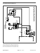
6. Disconnect hydraulic hose from lower fitting on gear
pump (Fig. 41).
7. Install hydraulic tester (pressure and flow) in series
with the gear pump fitting and the disconnected hose.
Make sure that tester flow arrow points from the pump
outlet port and toward the disconnected hose. Make
sure the flow control valve on the tester is fully
open.
8. Start engine and run at low idle speed (1300 RPM).
Check for any hydraulic leakage from test connections
and correct before proceeding with test.
9. With engine running, move throttle to full speed
(3100 to 3150 RPM).
10.Watch tester pressure gauge carefully while slowly
closing the flow control valve until 1000 PSI (69 bar) is
obtained. Do not close tester load valve fully. Verify with
a phototac that the engine speed remains 3100 to 3150
RPM while maintaining 1000 PSI (69 bar) on the tester
pressure gauge.
11.Observe flow gauge. Flow indication for a pump in
good condition is 5.2 GPM (19.7 LPM).
12.Open tester load valve and then stop engine. Record
test results.
13.Lower pump flow would result in reduced steering
and lift/lower circuit performance. If measured flow was
less than 4.4 GPM (16.6 LPM) or a pressure of 1000 PSI
(69 bar) cannot be obtained, check for restriction in the
pump inlet line. If inlet line is not restricted, remove gear
pump and repair or replace as necessary.
NOTE: Implement relief valve pressure can also be
tested with hydraulic tester (pressure and flow) in series
with the gear pump fitting and the disconnected hose.
Use pressure gauges on hydraulic tester and follow pro-
cedure for Implement Relief Pressure Test in this sec-
tion.
14.Relieve hydraulic system pressure (see Relieving
Hydraulic System Pressure in the General Information
section). Disconnect tester from deck lift valve fitting and
hydraulic hose. Connect hose to the control valve fitting.
1. Gear pump
2. Hydraulic hose
3. Lower fitting
Figure 41
2
3
1
Hydraulic
System