Form No. 3402-972 Rev A Heated (Only) Cab Kit 2015 and After Groundsmaster® 4000-D and 4100-D Rotary Mower Model No. 31231—Serial No. 316000001 and Up Model No. 31232—Serial No. 316000001 and Up Operator's Manual Safety WARNING CALIFORNIA Proposition 65 Warning This product contains a chemical or chemicals known to the State of California to cause cancer, birth defects, or reproductive harm. This product complies with all relevant European directives.
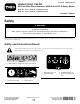
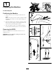
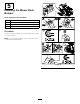
132-3600 5. Working light—20 A 1. Read the Operator's Manual for more information on fuses. 2. Headlight—25 A 6. Auxiliary power—15 A 3. Condenser fan and A/C clutch—30 A 4. Fan—25 A 7. Cab light—15 A 8. Windshield wipers—15 A 130-0594 130-0457 1. Left 1. Warning—read the Operator’s Manual; when sitting in the cab, always wear a seat belt; wear hearing protection. 2. Right 120–0250 1.
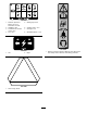
121-8378 1. Fan—off 3. Cold air 5. External air 7. Air conditioner—on (If equipped) 2. Fan—on full 4. Hot air 6. Internal air 8.
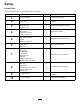
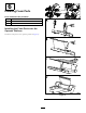
Setup Loose Parts Use the chart below to verify that all parts have been shipped. Procedure 1 2 3 4 5 6 7 8 9 10 Description Qty. Use No parts required – Prepare the machine. Safety decal 1 Apply the safety decal to the rear window.
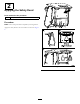
1 Preparing the Machine No Parts Required Positioning the Machine 1. Clear a location in your workspace under the hoist system. Note: Verify that your hoist system is capable of safely supporting the cab unit over the machine during the installation. 2. Move the machine to the workspace, lower the mower decks, shut off the engine, set the parking brake, and remove the key from the ignition switch. 3. Allow the engine coolant to cool and then drain the coolant from the machine; refer to the Service Manual.
2 Applying the Safety Decal Parts needed for this procedure: 1 Safety decal Procedure Note: Follow this procedure if required by local regulations. Apply the safety decal to the rear window as shown in Figure 2.
3 Installing Foam Seals Parts needed for this procedure: 1 Left foam seal 1 Right foam seal 1 Rear foam seal Installing the Side Foam Seals Remove the adhesive backer from the foam seals and apply them to the cab as shown in Figure 3. Note: Apply all foam seals in this procedure 13 mm (1/2 inch) away from the inside edge of the cab.
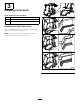
4 Installing the Step Plate Parts needed for this procedure: 1 Step plate 1 Step support 2 Bolt (3/8 x 3-1/2 inch) 2 Flange nut (3/8 inch) Procedure Remove the step support on the machine and then install the step support included in the cab kit as shown in Figure 4.
5 Installing the Mower-Deck Bumper Parts needed for this procedure: 1 Left bumper bracket 1 Right bumper bracket 2 Bumper 2 Flange nut (5/16 inch) Procedure Install the bumper assembly to the left and right mower decks as shown in Figure 5. Note: Use the existing hardware on the mower deck when you install the bumper bracket.
6 Installing Foam Parts Parts needed for this procedure: 1 Front seal 1 Tread foam 1 Rear seal Installing the Foam Parts onto the Operator Platform Install the foam parts to the operator platform (Figure 6).
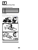
Securing the Cab to the Machine 7 Use the existing hardware to secure the cab to the machine (Figure 8). Installing the Cab Unit Parts needed for this procedure: 1 Cab unit 1 Floor tread 2 Straight fittings 2 Hose clamps 1 Side-seal cover 1 Side seal 1 Carriage bolt (3/8 inch) 1 Flange nut (3/8 x 3/4 inch) Connecting to the Lift Points Use the 4 lift points located on each corner of the cab unit (Figure 7). Important: Do not allow the lift system to contact the plastic headliner.
Installing the Floor Tread Install the Heater-Hose Fittings Install the floor tread onto the operator platform (Figure 9). Note: Ensure that you apply the adhesive strip to a clean surface with enough pressure to adhere the strip to the platform. Figure 10 Drain the coolant from the engine; refer to the Operator’s manual. Important: Allow the engine to cool and drain the coolant before performing the following procedure.
Routing the Heater Hoses Route the heater hoses underneath the machine and into the engine compartment (Figure 12). Figure 12 Important: Do not secure the hoses to hot or moving parts. Figure 11 Note: Store the engine plugs with the ROPS assembly to use when you remove the cab.
Connecting the Heater Hoses Connecting the Vent Hose Connect the heater hoses to the hose fittings. Use the existing hardware to connect the vent tube from the cab (Figure 14). Note: Connect the heater hose containing the red plug to the supply port and the heater hose containing the green plug to the return port on the engine as shown in Figure 13. Figure 14 Figure 13 Note: Store the hose plugs with the ROPS assembly to use when you remove the cab.
Installing the Side Seal Install the side seal to the cab (Figure 15).
Installing the Tank 8 Install washer-fluid tank to the machine (Figure 16). Installing the Washer-Fluid Tank Parts needed for this procedure: 1 Washer-fluid tank 2 Tank strap 1 Tank support 6 Carriage bolt (5/16 x 7/8 inch) 6 Flange nut (5/16 inch) 1 Wire harness Figure 16 Note: Use the existing hardware when you secure the tank support to the machine.
Routing and Connecting the Hose Connecting the Wire Harness Route the washer-fluid hose through the R-clamp under the machine and toward the back of the machine (Figure 17). Connect the wire harness for the washer-fluid bottle (Figure 18). Figure 18 Figure 17 Important: Do not secure the hoses to the hot or moving parts.
9 10 Connecting the Wire Harness Completing the Installation No Parts Required No Parts Required Procedure Procedure 1. Add coolant to the machine; refer to the Service Manual Locate the wire harness under the machine frame and connect it to the wire harness on the cab (Figure 19). 2. Check for leaks. 3. Route the drain hoses through the R-clamps on each side of the machine. 4. Check for parts that interfere with moving parts and make corrections before operating the machine. 5.
Product Overview Windshield Latch Controls Lift up the latches to open the windshield (Figure 21). Press the latch in to lock windshield to the open position. Pull out and down on the latch to close and secure the windshield. Cab Controls Figure 21 1. Windshield latch Figure 20 1. Windshield-wiper switch 4. Air-recirculation control 2. Temperature control 5. Power outlet Rear-Window Latch Lift up on the latches to open the rear window.
Maintenance Recommended Maintenance Schedule(s) Maintenance Service Interval Maintenance Procedure After the first 250 hours • Clean the cab air filters (replace them if they are torn or excessively dirty). Cleaning the Air Filter CAUTION If you leave the key in the ignition switch, someone could accidently start the engine and seriously injure you or other bystanders. Remove the key from the ignition before you do any maintenance.
Cleaning the Cab Storage Important: Use care around the cab seals and lights (Figure 24). If you are using a pressure washer, keep the washer wand at least 0.6 m (2 ft) away from the machine. Do not use the pressure washer directly on the cab seals and lights or under the rear overhang. Remove the cab unit for storage during the warmer months. Preparing the Machine for Cab Removal 2 1. Move the machine underneath the cab hoist, shut the engine off, and remove the key from the ignition. 2.
Declaration of Incorporation Model No. Serial No.
International Distributor List Distributor: Agrolanc Kft Asian American Industrial (AAI) B-Ray Corporation Brisa Goods LLC Casco Sales Company Ceres S.A. CSSC Turf Equipment (pvt) Ltd. Cyril Johnston & Co. Cyril Johnston & Co. Fat Dragon Femco S.A. FIVEMANS New-Tech Co., Ltd ForGarder OU G.Y.K. Company Ltd. Geomechaniki of Athens Golf international Turizm Hako Ground and Garden Hako Ground and Garden Hayter Limited (U.K.) Hydroturf Int. Co Dubai Hydroturf Egypt LLC Irrimac Irrigation Products Int'l Pvt Ltd.
The Toro Warranty A Two-Year Limited Warranty Conditions and Products Covered The Toro Company and its affiliate, Toro Warranty Company, pursuant to an agreement between them, jointly warrant your Toro Commercial product (“Product”) to be free from defects in materials or workmanship for two years or 1500 operational hours*, whichever occurs first. This warranty is applicable to all products with the exception of Aerators (refer to separate warranty statements for these products).