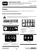
Form No. 3431-618 Rev A Heated (Only) Cab Kit 2015 and After Groundsmaster® 4000-D Rotary Mower Model No. 31232—Serial No. 400400001 and Up Operator's Manual Safety This product complies with all relevant European directives. For details, please see the Declaration of Incorporation (DOI) at the back of this publication. Safety and Instructional Decals Safety decals and instructions are easily visible to the operator and are located near any area of potential danger.
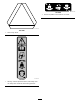
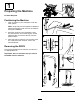
decal130-5356 130-5356 1. Use the foot pedal to move forward or in reverse. decal120-0250 120–0250 1. Slow-moving vehicle decal130-0594 130-0594 1. Warning—read the Operator’s Manual; when sitting in the cab, always wear a seat belt; wear hearing protection.
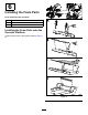
decal121-8378 121-8378 1. Fan—off 3. Cold air 5. External air 7. Air conditioner—on (If equipped) 2. Fan—on full 4. Hot air 6. Internal air 8.
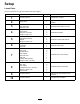
Setup Loose Parts Use the chart below to verify that all parts have been shipped. Procedure 1 2 3 4 5 6 7 8 9 10 Description Qty. Use No parts required – Prepare the machine. Safety decal 1 Apply the safety decal to the rear window.
1 Preparing the Machine No Parts Required Positioning the Machine 1. Clear a location in your workspace under the hoist system. Note: Verify that your hoist system is capable of safely supporting the cab unit over the machine during the installation. 2. Move the machine to the workspace, lower the mower decks, shut off the engine, set the parking brake, and remove the key from the ignition switch. 3.
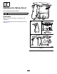
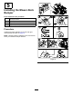
2 Applying the Safety Decal Parts needed for this procedure: 1 Safety decal Procedure Note: Follow this procedure if required by local regulations. Apply the safety decal to the rear window as shown in Figure 2.
3 Installing the Foam Seals Parts needed for this procedure: 1 Left foam seal 1 Right foam seal 1 Rear foam seal Installing the Side Foam Seals Remove the adhesive backer from the foam seals and apply them to the cab as shown in Figure 3. Note: Apply all foam seals in this procedure 13 mm (1/2 inch) away from the inside edge of the cab.
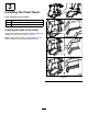
4 Installing the Step Plate Parts needed for this procedure: 1 Step plate 1 Step support 2 Bolt (3/8 x 3-1/2 inch) 2 Flange nut (3/8 inch) Procedure Remove the step support on the machine and then install the step support included in the cab kit as shown in Figure 4.
5 Installing the Mower-Deck Bumper Parts needed for this procedure: 1 Left bumper bracket 1 Right bumper bracket 2 Bumper 2 Flange nut (5/16 inch) Procedure Install the bumper assembly to the left and right mower decks as shown in Figure 5. Note: Use the existing hardware on the mower deck when you install the bumper bracket.
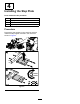
6 Installing the Foam Parts Parts needed for this procedure: 1 Front seal 1 Tread foam 1 Rear seal Installing the Foam Parts onto the Operator Platform Install the foam parts to the operator platform (Figure 6).
Securing the Cab to the Machine 7 Use the existing hardware to secure the cab to the machine (Figure 8). Installing the Cab Unit Parts needed for this procedure: 1 Cab unit 1 Floor tread 2 Straight fittings 2 Hose clamps 1 Side-seal cover 1 Side seal 1 Carriage bolt (3/8 inch) 1 Flange nut (3/8 x 3/4 inch) Connecting to the Lift Points Use the 4 lift points located on each corner of the cab unit (Figure 7). Important: Do not allow the lift system to contact the plastic headliner.
Installing the Floor Tread Install the Heater-Hose Fittings Install the floor tread onto the operator platform (Figure 9). Note: Ensure that you apply the adhesive strip to a clean surface with enough pressure to adhere the strip to the platform. g031337 Figure 10 Drain the coolant from the engine; refer to the Operator’s manual. Important: Allow the engine to cool and drain the coolant before performing the following procedure.
Routing the Heater Hoses Route the heater hoses underneath the machine and into the engine compartment (Figure 12). g031424 Figure 12 Important: Do not secure the hoses to hot or moving parts. g031330 Figure 11 Note: Store the engine plugs with the ROPS assembly to use when you remove the cab.
Connecting the Heater Hoses Connecting the Vent Hose Connect the heater hoses to the hose fittings. Use the existing hardware to connect the vent tube from the cab (Figure 14). Note: Connect the heater hose containing the red plug to the supply port and the heater hose containing the green plug to the return port on the engine as shown in Figure 13. g031404 Figure 14 g031338 Figure 13 Note: Store the hose plugs with the ROPS assembly to use when you remove the cab.
Installing the Side Seal Install the side seal to the cab (Figure 15).
Installing the Tank 8 Install washer-fluid tank to the machine (Figure 16). Installing the Washer-Fluid Tank Parts needed for this procedure: 1 Washer-fluid tank 2 Tank strap 1 Tank support 6 Carriage bolt (5/16 x 7/8 inch) 6 Flange nut (5/16 inch) 1 Wire harness g034424 Figure 16 Note: Use the existing hardware when you secure the tank support to the machine.
Routing and Connecting the Hose Connecting the Wire Harness Route the washer-fluid hose through the R-clamp under the machine and toward the back of the machine (Figure 17). Connect the wire harness for the washer-fluid bottle (Figure 18). g031444 Figure 18 g031417 Figure 17 Important: Do not secure the hoses to the hot or moving parts.
9 10 Connecting the Wire Harness Completing the Installation No Parts Required No Parts Required Procedure Procedure 1. Add coolant to the machine; refer to the Service Manual Locate the wire harness under the machine frame and connect it to the wire harness on the cab (Figure 19). 2. Check for leaks. 3. Route the drain hoses through the R-clamps on each side of the machine. 4. Check for parts that interfere with moving parts and make corrections before operating the machine. 5.
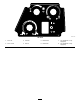
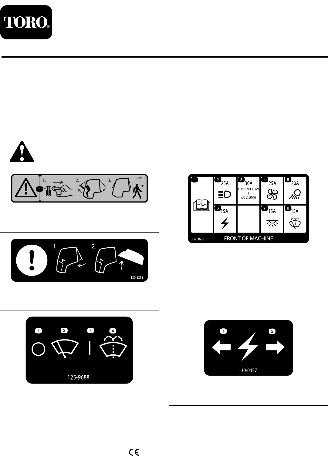
Windshield Latch Product Overview Lift up the latches to open the windshield (Figure 21). Press the latch in to lock windshield to the open position. Pull out and down on the latch to close and secure the windshield. Controls Cab Controls g008830 Figure 21 1. Windshield latch g030398 Figure 20 1. Windshield-wiper switch 4. Air-recirculation control 2. Temperature control 5. Power outlet Rear-Window Latch 3. Fan control Windshield-Wiper Switch Lift up on the latches to open the rear window.
Maintenance Recommended Maintenance Schedule(s) Maintenance Service Interval Maintenance Procedure After the first 250 hours • Clean the cab air filters (replace them if they are torn or excessively dirty). Cleaning the Air Filter CAUTION If you leave the key in the ignition switch, someone could accidently start the engine and seriously injure you or other bystanders. Remove the key from the ignition before you do any maintenance.
Cleaning the Cab Storage Important: Use care around the cab seals and Remove the cab unit for storage during the warmer months. lights (Figure 24). If you are using a pressure washer, keep the washer wand at least 0.6 m (2 ft) away from the machine. Do not use the pressure washer directly on the cab seals and lights or under the rear overhang. Preparing the Machine for Cab Removal 1. Move the machine underneath the cab hoist, shut the engine off, and remove the key from the ignition. 2.
Declaration of Incorporation Model No. Serial No.
EEA/UK Privacy Notice Toro’s Use of Your Personal Information The Toro Company (“Toro”) respects your privacy. When you purchase our products, we may collect certain personal information about you, either directly from you or through your local Toro company or dealer.
The Toro Warranty Two-Year or 1,500 Hours Limited Warranty Conditions and Products Covered Parts The Toro Company and its affiliate, Toro Warranty Company, pursuant to an agreement between them, jointly warrant your Toro Commercial product (“Product”) to be free from defects in materials or workmanship for 2 years or 1,500 operational hours*, whichever occurs first. This warranty is applicable to all products with the exception of Aerators (refer to separate warranty statements for these products).