Form No. 3435-462 Rev A Slope Sensor Kit Groundsmaster® 360 Multi-Purpose Machine Model No. 31250 Installation Instructions Safety Safety and Instructional Decals Safety decals and instructions are easily visible to the operator and are located near any area of potential danger. Replace any decal that is damaged or missing. decal140-2710 140-2710 1.
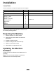
Installation Loose Parts Use the chart below to verify that all parts have been shipped. Description Use Qty. No parts required – Prepare the machine. No parts required – Update the machine software. Sensor module Bolt (1/2 x 1 inch) Nut (1/4 inch) Bolt (1/4 x 1-1/4 inch) Mounting bracket Wire harness Alarm Cable tie 1 2 2 2 1 1 1 4 Install the kit. No parts required – Calibrate the sensor. Decal 1 Install the decal.
Installing the Kit Installing the Sensor Module 1. Disconnect the battery. Refer to the Operator’s Manual for the procedure. 2. Move the seat forward. 3. Tilt the back cover forward or remove to gain access to the wires (Figure 1 or Figure 2). g321253 Figure 2 Machine with rollbar 1. Back cover 4. Install the sensor bracket to the frame with 2 bolts (1/2 x 1 inch); refer to Figure 3. Note: The holes in the frame are threaded. g321252 Figure 1 Machine with cab 1.
g321249 Figure 3 g321250 1. Sensor bracket 2. Bolt (1/2 x 1 inch) Figure 4 1. Bolt (1/4 x 1-1/4 inch) 5. Install the sensor to the sensor bracket with 2 bolts (1/4 x 1-1/4 inch) and 2 nuts (1/4 inch); refer to Figure 4. 3. Nut (1/4 inch) 2. Sensor 6. Plug the 90° connector into the sensor (Figure 5 and Figure 8). g321247 Figure 5 1. 90° connector 7. 4 Remove the control panel on the console or loosen and raise up the control panel (Figure 6 or Figure 7).
g321248 Figure 7 Machine with rollbar g321254 Figure 6 Machine with cab 1. Side cover 8. Remove the knockout for the alarm. 9. Install the alarm (Figure 7). Note: Installing the light and removing the decal area is for machines without an InfoCenter only. 10. Remove the area in the console decal for the light. 11. Install the light from the top of the console (Figure 7). 5 1. Light 3. Threaded ring 2. Alarm 4.
Routing the Wire Harness Calibrating the Sensor 1. Route the wire harness under the seat pan and along the along the existing wire harness in the cross channel (Figure 8). 2. Route the wire harness to the controls. 3. Install the middle connector to the machine wire harness connector labled TELEMATICS port or EXPANSION port (Figure 8). 4. Connect the wire harness to the light and the alarm (Figure 8). 1. While on a flat surface, remove the plug from the calibration connectors (Figure 9).
Note: The LED light at the top of the display screen (Figure 10) blinks as the sensor calibrates. ii. When the InfoCenter shows advisory 196, Slope Sensor Calibrated, the light no longer blinks, and the alarm beeps once, turn the ignition key to the OFF position. g315597 Figure 12 1. Calibration connectors 2. Plug g321267 Figure 10 1. LED light B. Installing the Decal Console light: i. The LED light (Figure 11) blinks as the sensor calibrates. ii.
Operation • No light—normal operating conditions Use the following procedures depending what your machine has installed. • Fast, flashing red light and audible alarm—steep • Slow, flashing red light—moderate slope slope; proceed to a more shallow slope. WARNING Slopes are a major factor related to loss-of-control and tip-over accidents, which can result in severe injury or death. Use extreme caution when operating the machine on a slope.