Form No. 3373-280 Rev A 72in Guardian® Recycler® Mower 72in Side-Discharge Mower Groundsmaster® 3280-D Traction Unit Model No. 31335—Serial No. 312000001 and Up Model No. 31336—Serial No. 312000001 and Up To register your product or download an Operator's Manual or Parts Catalog at no charge, go to www.Toro.com.
This product complies with all relevant European directives, for details please see the separate product specific Declaration of Conformity (DOC) sheet. Introduction This rotary-blade lawn cutting deck is mounted to a ride-on machine and is intended to be used by professional, hired operators in commercial applications. It is primarily designed for cutting grass on well-maintained lawns in parks, sports fields, and on commercial grounds.
Contents Replacing the Grass Deflector............................. 26 Introduction................................................................. 2 Safety ........................................................................... 4 Safe Operating Practices ....................................... 4 Toro Mower Safety ............................................... 5 Safety and Instructional Decals ............................. 7 Setup .....................................................................
Safety – Use only an approved container. – Never remove fuel cap or add fuel with engine running. Allow engine to cool before refueling. Do not smoke while refueling. This machine meets or exceeds CEN standard EN 836:1997, ISO standard 5395:1990, and ANSI B71.4-2004 specifications in effect at the time of production. – Never refuel or drain the machine indoors. • Check that operator's presence controls, safety switches and shields are attached and functioning properly.
Toro Mower Safety • Do not operate the mower under the influence of alcohol or drugs. • Lightning can cause severe injury or death. If lightning is seen or thunder is heard in the area, do not operate the machine; seek shelter. • Use care when loading or unloading the machine into a trailer or truck. • Use care when approaching blind corners, shrubs, trees, or other objects that may obscure vision.
• Keep your body and hands away from pin hole leaks or nozzles that eject hydraulic fluid under high pressure. Use paper or cardboard, not your hands, to search for leaks. Hydraulic fluid escaping under pressure can have sufficient force to penetrate the skin and cause serious injury. • Before disconnecting or performing any work on the hydraulic system, all pressure in the system must be relieved by stopping the engine and lowering the cutting units to the ground.
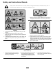
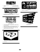
Safety and Instructional Decals Safety decals and instructions are easily visible to the operator and are located near any area of potential danger. Replace any decal that is damaged or lost. 93-7818 1. Warning—read the Operator's Manual for instructions on torquing the blade bolt/nut to 115-149 N-m (85-110 ft-lb). 120-6604 1. Thrown object hazard—keep bystanders away from the machine. 2. Cutting/dismemberment hazard of hand, mower blade—stay away from moving parts, keep all guards and shields in place.
93-6697 1. Read the Operator's Manual. 2. Add SAE 80w-90 (API GL-5) oil every 50 hours. 100-5622 1. Height of cut adjustment 117–4979 1. Entanglement hazard, belt—stay away from moving parts, keep all guards and shields in place. 107-2908 Model 31336 only 107-1622 Model 31336 only 1. Thrown object hazard—keep bystanders a safe distance from the machine. 2. Thrown object hazard—do not operate the mower with the deflector up or removed, keep the deflector in place. 3.
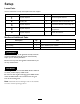
Setup Loose Parts Use the chart below to verify that all parts have been shipped. Procedure Description 1 2 3 4 5 Use Qty. No parts required – Secure the grass deflector Lift arm, right Lift arm, left 1 1 Install the lift arms to the traction unit No parts required – Connect the lift arms to the cutting unit No parts required – Connect the PTO shaft to the cutting unit gear box. No parts required – Grease the machine. Media and Additional Parts Description Use Qty.
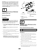
Important: If the 72 inch Side Discharge Cutting Unit, model 31336, is being mounted to a model 30307, 30308, 30309, 30343, 30344 or 30345 traction unit with a serial number prior to 311000301, the Cutting Unit Alignment Kit, part number 120–6599 must be installed to the cutting unit prior to being mounted to traction unit. 2 1 3 4 1 Securing the Grass Deflector 5 G018264 Figure 2 (Model 31336 only) 1. Grass Deflector 4. Left hand hook end of spring, place behind deck edge 2. Spring 5.
7. Hook the brake return spring to the tab on the lift arm (Figure 3). 4 3 5 2 1 Figure 3 1. Pivot pin 4. Brake return spring 2. Lift arm 3. Pivot bracket 5. Tab 8. Install the wheel and tire assembly. Torque the wheel nuts to 75-80 ft-lb (102-108 N-m). g018216 9. Repeat the procedure on the opposite side of the machine. Figure 4 1. Castor arm bracket 2. Hairpin cotter 3 4. Lift arm 5. Thrust washer 3. Clevis pin Connecting the Lift Arms to the Cutting Unit 4.
Product Overview Specifications Note: Specifications and design are subject to change without notice. Width of 72 inches (1.829 m) Cut Figure 5 1. PTO shaft 2. Bolts and locknuts 3. Gear case 4. Roll pin Height of Cut Adjustable from 1 to 5 inches (25 to 127 mm) in 1/2 inch (13 mm) increments Net Weight Model 31335–553 lb. (251 kg) Model 31336–643 lb.
Adjusting the Height-of-Cut Operation The height-of-cut is adjustable from 1 to 5 inches (25 to 127 mm) in 1/2 inch (13 mm) increments. To adjust the height-of-cut, position the castor wheel axles in the upper or lower holes of the castor forks and add or remove an equal number of spacers from the castor forks. 1. Start the engine and raise the cutting unit off the floor so that the height-of-cut can be changed. Stop the engine and remove the key after the cutting unit is raised. 2.
Note: The rear castor fork assembly does not need to be removed from the castor arm to change the height-of-cut. reverse the machines direction to pull any clippings away from the wheel/fork area. Front Castor Wheels 2. Remove or add ”C” shaped spacers at the narrow portion of the spindle shaft, below the castor arm, to get the desired height-of-cut. Make sure that the shims, not the spacers, contact the top and bottom of the castor arm. 1.
Adjusting the Anti-Scalp Rollers Whenever you change the height-of-cut, it is recommended to adjust the height of the anti-scalp rollers. 1. After adjusting the height-of-cut, adjust the rollers by removing the flange nut, bushing, spacer, and bolt (Figure 13). Figure 11 1.
1 2 3 4 Position B Use this position when bagging. Always align it with the blower opening. G008961 Figure 14 1. Unlock lever 2. Rotate the cam lock to increase or decrease locking pressure 3. Position the baffle 4. Lock lever Figure 16 Position C Positioning the Flow Baffle This is the full open position. The suggested use for this position is as follows. • Use in tall, dense grass mowing conditions. • Use in wet conditions. • Lowers the engine power consumption.
4. Using a short ruler, measure from the floor to the front tip of the blade. Rotate the blade tip to the rear and measure from the floor to the tip of the blade. 5. Subtract the front dimension from the rear dimension to calculate the blade pitch. 6. Adjust the shims, on the front or rear castor arms, to attain the required cutting unit pitch (Figure 18). 7. To ease measuring blade plane, raise the height of cut to the highest position; refer to Adjusting the Height of Cut. 8.
Select the Proper Height-of-Cut Setting to Suit Conditions Remove approximately 1 in. (25 mm) or no more than 1/3 of the grass blade when cutting. In exceptionally lush and dense grass, you may have to raise the height-of-cut to the next setting. Mow at Proper Intervals Under most normal conditions you will need to mow approximately every 4–5 days. But remember, grass grows at different rates at different times.
Maintenance Recommended Maintenance Schedule(s) Maintenance Service Interval Maintenance Procedure After the first 2 hours • Tighten the castor wheel nuts After the first 10 hours • Tighten the castor wheel nuts • Torque the blade bolts Before each use or daily • Lubricate the castor arm bushings • Lubricate the castor wheel bearings • Check the blades Every 50 hours • • • • • • Check the gear box lubricant Lubricate the grease fittings Tighten the castor wheel nuts Torque the blade bolts Check th
Lubrication Service Interval: Every 50 hours The machine has grease fittings that must be lubricated regularly with No. 2 General Purpose Lithium Base Grease. If the machine is operated under normal conditions, lubricate all bearings and bushings after every 50 hours of operation or immediately after every washing. 1. Lubricate the following areas: Figure 21 • Castor fork shaft bushings (4)(Figure 19) • Lift arm pivots, rear (2) (Figure 22) Figure 22 Figure 19 2.
Figure 24 1. Lift arm 3. Hairpin cotter 2. Clevis pin 4. Castor arm bracket Figure 23 3. Roll the cutting unit away from the traction unit, separating the male and female sections of the PTO shaft (Figure 25). 1. Dipstick/fill plug Pre Maintenance Important: The fasteners on the covers of this machine are designed to remain on the cover after removal.
Servicing the Bushings in the Castor Arms line up with the holes in the castor arm bracket and the height of cut rod can be inserted into the lift arm pads (Figure 26). The castor arms have bushings pressed into the top and bottom of the tube and after many hours of operation, the bushings will wear. To check the bushings, move the castor fork back and forth and from side to side. If the castor spindle is loose inside the bushings, the bushings are worn and must be replaced. 5.
of the blade at the same position as in step 2 The difference between the dimensions obtained in steps 2 and 3 must not exceed 1/8 inch (3 mm). If the dimension exceeds 1/8 inch (3 mm), replace the blade because it is bent; refer to Removing the Cutting Blade. Removing and Installing the Blade(s) The blade must be replaced if a solid object is hit, the blade is out-of-balance, worn, or bent. Always use genuine Toro replacement blades to ensure safety and optimum performance.
Inspecting and Sharpening the Blade(s) Service Interval: Before each use or daily Every 50 hours DANGER A worn or damaged blade can break, and a piece of the blade could be thrown into the operator's or bystander's area, resulting in serious personal injury or death. Figure 31 • Inspect the blade periodically for wear or damage. 1. Cutting edge 3. Wear/slot forming 2. Curved area/sail 4. Crack WARNING • Do not try to straighten a blade that is bent.
Replacing the Drive Belt Checking and Correcting Mismatch of Blades The blade drive belt, tensioned by the spring loaded idler pulley, is very durable. However, after many hours of use, the belt will show signs of wear. Signs of a worn belt are: squealing when belt is rotating, blades slipping when cutting grass, frayed edges, burn marks and cracks. Replace the belt if any of these conditions are evident. If there is mismatch between the blades, the grass will appear streaked when it is cut.
Figure 35 1. Belt routing Figure 36 5. Install the belt covers. 1. Bolt 5. Spring installed 2. Spacer 6. Grass Deflector 3. Locknut 7. L end of spring, place behind deck edge before installing bolt 4. Spring 8. J hook end of spring Replacing the Grass Deflector WARNING An uncovered discharge opening could allow the lawn mower to throw objects in the operator's or bystander's direction and result in serious injury. Also, contact with the blade could occur.
Notes: 27
The Toro Total Coverage Guarantee A Limited Warranty Conditions and Products Covered The Toro Company and its affiliate, Toro Warranty Company, pursuant to an agreement between them, jointly warrant your Toro Commercial product (“Product”) to be free from defects in materials or workmanship for two years or 1500 operational hours*, whichever occurs first. This warranty is applicable to all products with the exception of Aerators (refer to separate warranty statements for these products).