
Service Manual

DRIVE SYSTEMS
5 - 24 Single Stage Snowthrower Service Manual
Figure 118 0217-069
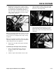
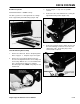
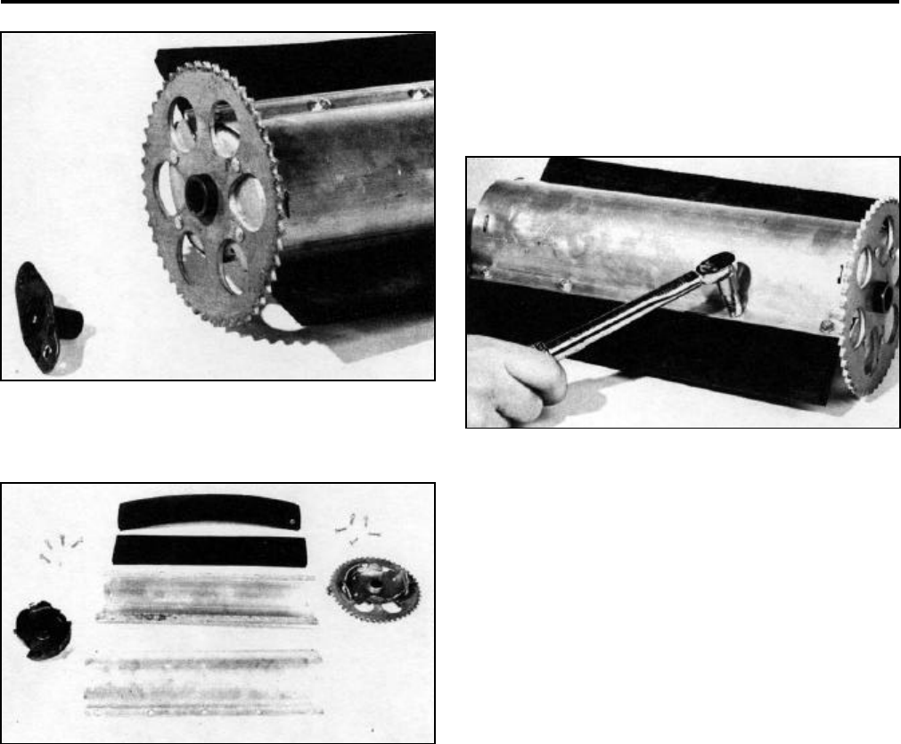
6. Remove all screws retaining the rubber paddles to
the rotor shells (Figure 119).
Figure 119 0217-070
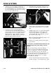
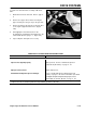
7. Remove the impeller sprocket/end cap assembly
from both rotor shells (Figure 119).
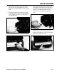
8. When replacing with the new impeller sprocket/
end cap assembly, be certain to align the small
tabs on the end plate with the slots in the rotor
shells (Figure 117). The same procedure is also
used on the right hand end cap.
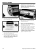
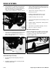
9. After fitting the new end caps in position, slide the
paddles into position and reinstall the screws
(Figure 120). The screws that hold the impeller
assembly together should be torqued to 15 in·lbs.
(DO NOT OVERTORQUE!)
Figure 120 0217-071
10. When replacing the end caps, the rotor shafts
should also be replaced.
11. Slide the rotor shell assembly back into the
housing of the snowthrower and align the rotor
shafts with the four mounting holes. Tighten all
four carriage bolts (Figure 116).
12. Reinstall the stripper assembly over the impeller
sprocket with both self-tapping screws (Figure
115). (Note: The mounting holes for the stripper
assembly are slotted. Rotate the impeller
assembly to assure the impeller sprocket moves
freely within the stripper assembly.) Should the
stripper assembly be worn, replace.