
Service Manual

Single Stage Snowthrower Service Manual 9 - 21
GAS POWER SHOVEL
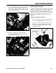
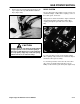
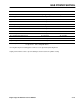
5. Remove the rope from the pulley and measure the
rope. Replace the rope with #4 Diamond Braid
Rope (Figure 234).
Figure 234 0406-051
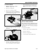
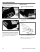
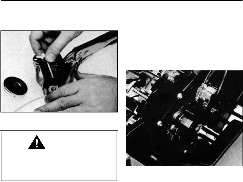
DRIVE SYSTEM
The Toro Gas Power Shovel drive system consists of a
crankshaft adapter, a rubber drive coupling, a series of
three drive gears, and a rotor.
Engine power is transferred from the engine crankshaft
and crankshaft adapter (through the rubber drive
coupling) through the gear train to the rotor (Figure
235).
Figure 235 0406-052
To service the drive system, assure that the rubber
drive coupling is fully seated on the crankshaft adapter
and into the drive gear assembly.
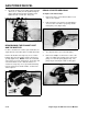
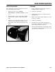
To check the gear train, remove the nut on the drive
side of the rotor (Figure 236) and remove the six
Phillips screws from the gear carrier plate (Figure 237).
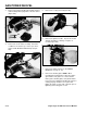
Carefully remove the rope pulley by slowly pulling
it straight upwards. The recoil starter spring is
attached to a small plastic boss on the underside
of the rope pulley. Injury may result if the spring
unwinds from the recoil starter housing.
CAUTION