Form No. 3415-706 Rev B EU Light Kit 2015 and After Groundsmaster® 4010/4110 Series Rotary Mower with Cab Model No. 31504 Installation Instructions Note: Install the light adapter kit, model 30691, on machines that are 2017 and newer. Contact your authorized Toro distributor for the light adapter kit. WARNING CALIFORNIA Proposition 65 Warning This product contains a chemical or chemicals known to the State of California to cause cancer, birth defects, or reproductive harm.
Procedure Description 5 Headlamp bracket—right (for Models 30605 and 30609) Headlamp bracket—left (for Models 30605 and 30609) Rubber grommet (for Models 30605 and 30609) Headlamp bracket (for Models 30643, 30635, 30644 and 30636) Headlamp bracket—right (for Models 30604 and 30608) Headlamp bracket—left (for Models 30604 and 30608) Screw (1/2 x 1 inch) Locknut (1/2 inch) Headlamp—right Headlamp—left Wire harness, headlight Harness clip 6 7 8 Use Qty. 1 1 2 2 1 Install the headlights.
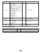
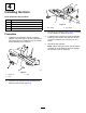
1 Disconnecting the Battery No Parts Required Procedure 1. Park the machine on a level surface, engage the parking brake, lower the cutting units, shut off the engine, and remove the key. g021747 Figure 1 CAUTION 1. Steering tower cover If you leave the key in the ignition switch, someone could accidently start the engine and seriously injure you or bystanders. 2. Secure the flasher mount to the steering tower (Figure 2) with 2 screws (1/4 x 5/8 inch) and flange nuts (1/4 inch).
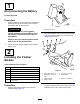
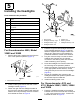
3 Installing the Turn Signal and Hazard Switches Parts needed for this procedure: 1 Switch, turn signal 1 Switch, hazard 1 Wire harness, platform Procedure g021714 1. From the under side of the steering tower dash panel, press the plugs out of the holes shown in Figure 3. Figure 4 1. Hazard switch Note: On models 30643, 30635, 30644, and 30636. the turn signal and hazard switches are already installed on the machine. Skip to Step 4. 2. Turn signal switch 3.
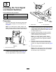
4 Installing the Horn Parts needed for this procedure: 1 Horn 1 Bolt (5/16 x 3/4 inch) 1 Flange nut (5/16 inch) 1 Horn switch 1 Rubber horn button g021715 Figure 6 1. Horn switch Procedure 1. Install the horn bracket to the tab, under the platform, with a bolt (5/16 x 3/4 inch) and locknut (3/8 inch) (Figure 5). Rotate the horn so it faces toward the back of the machine. 2. Horn button 3. Secure the horn switch to the tower by threading on the rubber horn button (Figure 6). 4.
5 Installing the Headlights Parts needed for this procedure: 1 Headlamp bracket—right (for Models 30605 and 30609) 1 Headlamp bracket—left (for Models 30605 and 30609) 2 Rubber grommet (for Models 30605 and 30609) 2 Headlamp bracket (for Models 30643, 30635, 30644 and 30636) 1 Headlamp bracket—right (for Models 30604 and 30608) 1 Headlamp bracket—left (for Models 30604 and 30608) 2 Screw (1/2 x 1 inch) 2 Locknut (1/2 inch) 1 Headlamp—right 1 Headlamp—left 1 Wire harness, headlight 2 H
For Groundsmaster 4100, Models 30604 and 30608 1. Remove the 2 bolts, washers and nuts from the front of the operator's platform (Figure 10). g021734 Figure 10 1. Bolt, washer and nut (2) g028462 Figure 9 1. Wire harness 2. Headlight assembly—right 5. Screw (1/2 x 1 inch) 3. Headlight bracket (2) 6. Locknut (1/2 inch) 2. 2. Fasten the right and left headlight brackets to the front of the operator's platform with the bolts, washers and nuts previously removed.
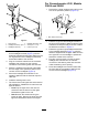
g013035 Figure 12 1. Plate 2. Right cover 2. Remove the 6 screws that secure the right cover to the right side of the control arm (Figure 12). 3. From inside the control arm switch panel, press the plug out of the hole in the side of the control panel (Figure 13). g021708 Figure 11 1. Wire harness 4. Headlight bracket —right 2. Headlight assembly—right 5. Headlight assembly—left 3. Harness clip 6. Headlight bracket—left 6.
7 Installing the Rear Lamps Parts needed for this procedure: 1 Light mount—left 1 Light mount—right 2 Rear lamp assembly 2 Jumper wire harness 2 Harness clip Procedure 1. g021710 Figure 15 Remove the top bolt, washer and nut securing the rear bumper bracket to the left frame rail (Figure 14). Retain the bolt, washer and nut. 1. Jumper wire harness 4. Lamp mount—left 2. Lamp mount—right 5. Rear lamp (2) 3. Harness clip 3.
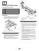
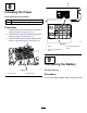
8 Installing the Fuses Parts needed for this procedure: 2 Fuse (10 A) 1 Fuse (15 A) Procedure 1. Insert a fuse (10 A) into fuse-block slot at row 3, column A (Figure 16 and Figure 17). 2. Insert a fuse (15 A) into fuse-block slot at row 4, column A (Figure 16 and Figure 17). 3. Insert the other fuse (10 A) into fuse-block slot at row 4, column D (Figure 16 and Figure 17). g213810 Figure 17 1. Cover 3. Fuse (15 A) location on decal 2.
Horn Operation Press the horn button to activate the horn (Figure 19). Controls Aiming the Headlights Light Switch Press the light switch (Figure 18) to the On position to activate the head lamps. g021721 Figure 18 1. Light switch Hazard Switch Press the hazard switch (Figure 19) to the On position to activate the front and rear flashing hazard lights. g021733 Figure 19 1. Hazard switch 2. Turn signal switch 3.
Declaration of Incorporation The Toro Company, 8111 Lyndale Ave. South, Bloomington, MN, USA declares that the following unit(s) conform(s) to the directives listed, when installed in accordance with the accompanying instructions onto certain Toro models as indicated on the relevant Declarations of Conformity. Model No. 31504 Serial No.