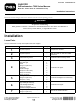
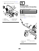
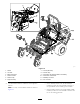
Form No. 3414-544 Rev A Light Kit Groundsmaster® 7200 Series Mowers Model No. 31508—Serial No. 400000000 and Up Installation Instructions Determine the left and right sides of the machine from the normal operating position. WARNING CALIFORNIA Proposition 65 Warning This product contains a chemical or chemicals known to the State of California to cause cancer, birth defects, or reproductive harm. Installation Loose Parts Use the chart below to verify that all parts have been shipped.
Procedure 8 9 10 11 12 Description Use Qty. Lever 1 Horn Carriage bolt (5/16 x 5/8 inch) Flange nut (5/16 inch) Wiring harness 20A fuse Relay Flasher module 20 kmp decal Serial plate 1 1 1 1 1 1 1 3 1 No parts required – 1 Install the control lever. Install the front light brackets, headlights, and horn. Install the wire harness. Install the decals. Finish the installation.
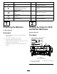
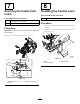
2. Drill the holes as shown in Figure 2. 1 4. Drill the holes as shown in Figure 4. 2 1 4 2 3 3 g037927 g037927 g038182 Figure 4 Front view of the foot rest g038182 Figure 2 Front of the machine 1. 40.6 cm (16 inches) 3. 25 mm (1 inch) 2. 18.6 cm (7-5/16 inches) 4. 13/32 inch diameter 1. 26 cm (10-1/4 inches) 3. 11.4 cm (4-1/2 inches) 2. 3.2 cm (1-1/4 inch) 3 3. Drill the holes for the horn as shown in Figure 3.
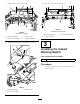
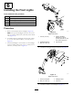
Installing the Rear Lights Parts needed for this procedure: g004495 Figure 5 1. Control panel side cover 2. Latches 2. Locate and remove the knockout plug located towards the front of the control panel under the decal (Figure 6). 1 Left rear light 1 Right rear light 4 U-bolt 8 Flange nut (3/8 inch) 1 Light plate 1 Center rear light 2 Bolt (#10 x 7/8 inches) 2 Bolt (1/4 x 3/4 inch) 4 Flange nut (#10) Procedure 1.
2. Install the light plate and center rear light (Figure 8). 5 Note: You may need an extra person to hold the light plate as you secure it to the machine. Installing the Headlight-Mount Assembly Parts needed for this procedure: 1 Headlight-mount assembly 2 Flange nut (3/8 inch) 2 Bolt (3/8 x 1 inch) Procedure Install the headlight-mount assembly to the front of the machine with 2 bolts (3/8 x 1 inch) and 2 flange nuts (3/8 inch); refer to Figure 9. g207375 Figure 8 1. Light plate 4.
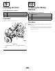
1 6 2 3 41 5 Installing the Front Lights 3 Parts needed for this procedure: 8 Locknut (1/4 inch) 1 Right headlight assembly 1 Leftt headlight assembly 8 Bolt (1/4 x 3/4 inch) 2 Optional headlight extension Procedure g037930 1. Remove the shields from the headlights (Figure 11). g037930 Figure 10 Right side shown Note: The optional headlight extensions are for the 183 cm (72 inch) and 254 cm (100 inch) mower decks only (Figure 10). 2.
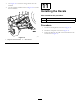
8 Securing the Caster-Fork Latch Installing the Control Lever Parts needed for this procedure: 1 Parts needed for this procedure: 1 Flange bolt (3/8 x 1-1/2 inches) 1 Flange nut (3/8 inch) Lever Procedure 1. Remove the existing left handle and retain the washers and bolts. Procedure 2. Install the new handle with the existing washers and bolts (Figure 13). Important: This procedure is only for 254 cm (100 inch) mower decks. Secure the caster-fork latch as shown in Figure 12.
9 10 Installing the Horn Installing the Wiring Harness Parts needed for this procedure: 1 Horn 1 Carriage bolt (5/16 x 5/8 inch) 1 Flange nut (5/16 inch) Parts needed for this procedure: Procedure 1 Wiring harness 1 20A fuse 1 Relay 1 Flasher module Install the horn as shown in Figure 14. Procedure Note: Do not attach the black (negative) lead until the whole kit is installed. 1.
g207446 Figure 15 7. License plate lamp 1. Switch 2. 10A fuse 8. Left rear lamp 3. Blade connectors 9. Connect the red (positive) leads to the battery. 4. Flasher module 5. Flasher relay 10. Control-lever connections 11. Headlamp connector 6. Right rear lamp 12. Horn connector • If the Auxiliary Power Unit (model 30382) is 2. Use the blade connectors under the control panel as follows: installed, connect the correct blade connector to the open blade on the auxiliary power module.
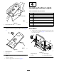
3. Use Figure 15 to route the wiring harness into the machine. 11 4. Use the magnetic holders shown in Figure 16 to secure the wire harness. 1 2 Installing the Decals 1 Parts needed for this procedure: 3 20 kmp decal 1 Serial plate Procedure 1. Install the 20 kmp decals as shown in Figure 17. 2. Install the serial plate as shown in Figure 17. g037928 3. Stamp the date into the side of the metal frame in the area shown in Figure 17. g037928 Figure 16 1. Magnetic harness holders 2.
g189862 Figure 17 1. 20 kpm decal 2. 3.8 cm (1-1/2 inches) 5. For German customers, stamp the required information into the side of the frame in this area. 6. 7.6 cm (3 inches) 3. 6 mm (1/4 inch) 7. 12.7 cm (1-1/4 inches) 4. Serial number decal 12 Finishing the Installation No Parts Required Procedure 1. Attach the negative battery cable and the black (negative) lead to the battery. 2. Latch the engine cover. 3. Test all the functions of the kit.
Operation Operating the Switches • The hazard warning switch operates the hazard warning lights and will work whether the ignition is switched to the ON or OFF position (Figure 18). g189974 Figure 18 g185894 Figure 19 1. Light switch 1. Headlamp and dipped-beam switch – Press the side of the rocker switch with the hazard warning symbol to operate the hazard warning lights. 3. Horn button 2. Direction-indicator switch – Press the other side of the rocker switch to turn off the hazard warning lights.
Notes:
Notes:
Notes:
The Toro Warranty A Two-Year Limited Warranty Conditions and Products Covered The Toro Company and its affiliate, Toro Warranty Company, pursuant to an agreement between them, jointly warrant your Toro Commercial product (“Product”) to be free from defects in materials or workmanship for two years or 1500 operational hours*, whichever occurs first. This warranty is applicable to all products with the exception of Aerators (refer to separate warranty statements for these products).