Form No. 3413-563 Rev C Flow Divider Kit Serial Number 400000000 and After Groundsmaster® 4100 Series Traction Unit Model No. 31526 Installation Instructions Note: Determine the left and right sides of the machine from the normal operating position. Safety Safety and Instructional Decals Safety decals and instructions are easily visible to the operator and are located near any area of potential danger. Replace any decal that is damaged or missing. decal132-6104 132-6104 1.
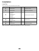
Installation Loose Parts Use the chart below to verify that all parts have been shipped. Procedure 1 2 3 4 5 6 Description Use Qty. No parts required – Prepare the machine. No parts required – Remove the hydraulic lines. Flow divider Hex-head bolt Flange nut Traction-motor tube Tube manifold Return hose Cross hose Rear traction hose Toggle switch Wire harness 4WD function decal Relay Cable tie 1 2 2 1 1 1 1 1 1 1 1 1 1 No parts required – Install the hydraulic components.
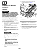
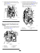
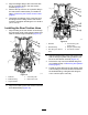
6. 1 Remove the controller cover and the right console cover as shown in Figure 1. Preparing the Machine No Parts Required Procedure CAUTION If you leave the key in the ignition switch, someone could accidently start the engine and seriously injure you or other bystanders. Remove the key from the ignition switch before you perform any maintenance. Important: Use lifting and support equipment with a capacity of 1300 kg (5,000 lb) or greater. g034560 Figure 1 Important: Cap or plug any disconnected 1.
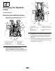
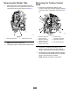
2 Removing the Hydraulic Lines No Parts Required Removing the Hydraulic Hoses 1. Align a drain pan below the forward end of the hydraulic-pressure hose (Figure 2). g212936 Figure 3 g212935 Figure 2 1. Rear traction manifold 2. Traction-control hose 3. Hydraulic pump 5. Rear traction hose 6. Traction motor 7. Divider tube 4. Hydraulic-pressure hose 8. Combination manifold 2.
6. Pull the rear traction hose through the hose support bracket, and remove the hose from the machine (Figure 4). Note: Discard the rear traction hose. 2. Remove the clamp-block halves (Figure 5). 3. Remove the 2 bolts and 2 flange nuts that secure the support bracket to the chassis bracket, and remove the support bracket (Figure 6). Note: Discard the bolts, nuts, clamp-block halves, and support bracket. g212933 Figure 4 1. Hose support bracket 7. 2.
Removing the Divider Tube 1. Removing the Traction-Control Hose Remove the tube nut of the divider tube from the T-fitting in the front, right traction motor, and remove the tube from the machine (Figure 7). 1. Remove the inboard-hose fitting for the traction-control hose from the hydraulic fitting in port (CH1) of the combination manifold (Figure 8). g212937 Figure 8 g212934 Figure 7 1. Tube nut (divider tube) 2. T-fitting (traction motor) Note: Discard the divider tube. 2. 1.
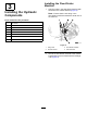
Installing the Flow-Divider Manifold 3 1. Installing the Hydraulic Components Align the holes in the flow-divider manifold with the holes in the chassis bracket (Figure 9). Note: Ensure that the 45º fitting in the flow-divider manifold is toward the center line of the machine. Parts needed for this procedure: 1 Flow divider 2 Hex-head bolt 2 Flange nut 1 Traction-motor tube 1 Tube manifold 1 Return hose 1 Cross hose 1 Rear traction hose g021371 Figure 9 1. Flange nuts 3.
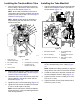
Installing the Traction-Motor Tube 1. Installing the Tube Manifold Align the tube nuts for the traction-motor tube to the T-fitting in the traction motor and the 90º fitting in the flow divider (Figure 10). 1. Align the forward tube nut for the tube manifold with the check adapter located in port CH1 of the flow divider (Figure 11). Note: Ensure that the traction-motor tube is routed above the hydraulic-pressure hose of the hydraulic pump; refer to step 2 of Removing the Hydraulic Hoses (page 4).
Installing the Return Hose 1. Installing the Cross Hose Align the straight fitting of the return hose with the threaded fitting of the tube manifold (Figure 12). 1. Align the 90° fitting of the cross hose through the cushioned guide in the support bracket, and slide the hose through the bracket (Figure 13). Note: Ensure that the return hose is routed above the hydraulic-pressure hose of the hydraulic pump; refer to step 2 of Removing the Hydraulic Hoses (page 4). g212925 Figure 13 1.
3. Align the straight fitting of the cross hose with the 45° hydraulic fitting in the rear traction manifold (Figure 14). 4. Remove the cap from the 45° hydraulic fitting in the rear traction manifold that you installed in step 3 of Removing the Traction-Control Hose (page 6). 5. Thread the hose fittings of the cross hose onto the fittings of the T-fitting and the rear traction manifold, and tighten the fittings to 51 to 63 N∙m (37 to 47 ft-lb). Installing the Rear Traction Hose 1.
Installing the Hydraulic-Pressure Hose 1. 2. Remove the plug from the end of the hydraulic-pressure hose that you installed in step 3 of Removing the Hydraulic Hoses (page 4). 4. Thread the straight fitting of the hydraulic-pressure hose onto the 45° hydraulic fitting in the flow-divider manifold (Figure 18). 5. Align the 45° fitting of the pressure hose with the straight fitting in the hydraulic pump (Figure 19).
2. 4 Place the 4WD function decal over the drilled hole (Figure 21). Installing the Switch Parts needed for this procedure: 1 Toggle switch 1 Wire harness 1 4WD function decal Procedure 1. Drill a 13 mm (1/2 inch) hole in the center console; refer to Figure 20 for the appropriate orientation. Important: Use caution to not hit any components or wires underneath the console with the drill bit. g205310 Figure 21 3.
4. Secure the red wire labeled BYPASS ENGAGE SWITCH 2 to the override switch center terminal number 2 (Figure 22 and Figure 23). 5. Secure the gray wire labeled BYPASS ENGAGE SWITCH 1 to the override switch rear terminal number 1 (Figure 22 and Figure 23). 6. Route the toggle switch with the connected wire harness into the rear of the center console (Figure 24). Important: Incorrect switch wiring can result in damage to the hydraulic system.
Discard the tabbed washer included with the toggle switch. 5 Installing the Kit to the Wire Harness Parts needed for this procedure: 1 Relay 1 Cable tie Procedure 1. Plug the relay connector into the relay as shown in Figure 27. g274109 Figure 26 1. Hex locknut 2. Washer (15/32 inch) 3. Hex locknut 4. Toggle switch g035962 Figure 27 2. 14 Connect the relay to the relay mount with a cable tie as shown in Figure 28.
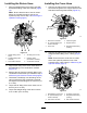
6 Completing the Installation No Parts Required Checking for Hydraulic Leaks WARNING Hydraulic fluid escaping under pressure can penetrate skin and cause injury. g035966 Figure 28 3. Unlatch the seat and locate the remaining loose wire harness ends below the back right corner of the now exposed frame crossbar. • Make sure that all hydraulic fluid hoses and lines are in good condition and all hydraulic connections and fittings are tight before applying pressure to the hydraulic system. 4.
Operation WARNING Incorrect battery cable routing could damage the machine and cables causing sparks. Sparks can cause the battery gasses to explode, resulting in personal injury. 4WD Switch Press and hold the 4WD toggle switch forward to momentarily activate the 4WD function of the machine. • Always disconnect the negative (black) battery cable before disconnecting the positive (red) cable. • Always connect the positive (red) battery cable before connecting the negative (black) cable. g035443 5.
Schematics g212898 Hydraulic Schematic (Rev.
Notes:
Notes: