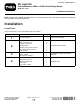
Form No. 3420-815 Rev C EU Light Kit Groundsmaster® 4000 or 4100 Series Rotary Mower Model No. 31543 Installation Instructions Note: Install the light adapter kit, Model 30691, on machines that are 2017 and newer. Contact your authorized Toro distributor for the light adapter kit. Installation Loose Parts Use the chart below to verify that all parts have been shipped.
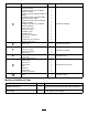
Procedure Description 5 Headlamp bracket—right (for Models 30605 and 30609) Headlamp bracket—left (for Models 30605 and 30609) Rubber grommet (for Models 30605 and 30609) Headlamp bracket (for Models 30643, 30635, 30644 and 30636) Headlamp bracket—right (for Models 30604 and 30608) Headlamp bracket—left (for Models 30604 and 30608) Screw (1/2 x 1 inch) Locknut (1/2 inch) Headlamp—right Headlamp—left Wire harness, headlight Harness clip Carriage bolt (1/4 x 5/8 inch) Flange nut (1/4 inch) 6 7 8 9 10 Use
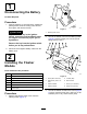
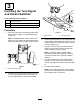
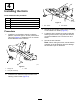
1 Disconnecting the Battery No Parts Required Procedure 1. Park the machine on a level surface, engage the parking brake, lower the cutting units, shut off the engine, and remove the key. g021747 Figure 1 CAUTION 1. Steering tower cover If you leave the key in the ignition switch, someone could accidently start the engine and seriously injure you or bystanders. 2. Secure the flasher mount to the steering tower (Figure 2) with 2 screws (1/4 x 5/8 inch) and flange nuts (1/4 inch).
3 Installing the Turn Signal and Hazard Switches Parts needed for this procedure: 1 Switch, turn signal 1 Switch, hazard 1 Wire harness, platform Procedure g021714 1. From the under side of the steering tower dash panel, press the plugs out of the holes shown in Figure 3. Figure 4 1. Hazard switch Note: On Models 30643, 30635, 30644, and 30636. the turn signal and hazard switches are already installed on the machine. Skip to Step 4. 2. Turn signal switch 3.
4 Installing the Horn Parts needed for this procedure: 1 Horn 1 Bolt (5/16 x 3/4 inch) 1 Flange nut (5/16 inch) 1 Horn switch 1 Horn button, rubber g021715 Figure 6 1. Horn switch Procedure 1. Install the horn bracket to the tab, under the platform, with a bolt (5/16 x 3/4 inch) and locknut (3/8 inch) (Figure 5). Rotate the horn so it faces toward the back of the machine. 2. Horn button 3. Secure the horn switch to the tower by threading on the rubber horn button (Figure 6). 4.
washers and nuts previously removed. Position the brackets as shown in Figure 8.
For Groundsmaster 4010 and 4110, Models 30643, 30635, 30644 and 30636 1. Fasten the headlight brackets to the existing brackets on the front of the cab with screws (1/2 x 1 inch) and locknuts (1/2 inch). Position the brackets as shown in Figure 9. 2. Install a rubber grommet into the hole in each headlight bracket (Figure 9). 3. Install the headlight bracket to the cab with 2 carriage bolts (1/4 x 5/8 inch) and 2 flange nuts (1/4 inch). 7.
g013035 Figure 12 1. Plate 2. Right cover 2. Remove the 6 screws that secure the right cover to the right side of the control arm (Figure 12). 3. From inside the control arm switch panel, press the plug out of the hole in the side of the control panel (Figure 13). g021708 Figure 11 1. Wire harness 4. Headlight bracket —right 2. Headlight assembly—right 5. Headlight assembly—left 3. Harness clip 6. Headlight bracket—left 6.
7 Installing the Rear Lamps Parts needed for this procedure: 1 Light mount—left 1 Light mount—right 2 Rear lamp assembly 2 Harness clip Procedure 1. g246062 Remove the top bolt, washer and nut securing the rear bumper bracket to the left frame rail (Figure 14). Retain the bolt, washer and nut. Figure 15 1. Rear lamp (2) 3. Harness clip 2. Lamp mount—right 4. Lamp mount—left 3. Mount the rear lamp to lamp mount with bolts and nuts included with the lamp (Figure 15).
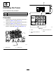
8 Installing the Fuses Parts needed for this procedure: 2 Fuse (10 A) 1 Fuse (15 A) Procedure 1. Insert a fuse (10 A) into fuse-block slot at row 3, column A (Figure 16 and Figure 17). 2. Insert a fuse (15 A) into fuse-block slot at row 4, column A (Figure 16 and Figure 17). 3. Insert the other fuse (10 A) into fuse-block slot at row 4, column D (Figure 16 and Figure 17). g213810 Figure 17 1. Cover 2. Fuse (10 A) locations on decal g213809 Figure 16 1. Fuses (10 A) 2. Fuses (15 A) 10 3.
9 Installing the License Plate Mount Parts needed for this procedure: 2 Screw (#10 x 5/8 inch) 2 Locknut (#10) 1 Plate mount 1 Wire harness 1 Light 2 Cable ties 1 Harness clip 2 Jumper wire harness Procedure 1. 2. Open the hood. g244972 Figure 18 Remove the cotter pins from the catch rods on each side of the hood. 3. Remove the 2 cotter pins securing the rear hood to the frame pivots and lift the hood off the machine. 4.
g262753 Figure 20 1. Right side connector 2. Jumper wire harness 6. Left lamp 3. Light connector 7. Light connector 4. Right lamp 8. Left side connector 17. g245964 5. Tail light connectors Figure 19 Secure the remaining wires with the cable ties. Important: Ensure that the wires are clear of all hot, sharp or moving components. 1. Hood 4. Harness clip 2. Light 5. Tail-light connector 18. Close and secure the hood. 3. Plate mount 6. Connector for machine harness 19.
10 11 Installing the Decals Connecting the Battery Parts needed for this procedure: No Parts Required 3 Decal Procedure Connect the negative battery cable to the battery post. Procedure Note: Only install the decals when they are required for your machine. Clean the area on the machine for the decals and install the decals as shown in Figure 21. g239580 Figure 21 1. Decal 3. 21.6 cm (8-1/2 inches) 2. Plate mount 4. 16.
Horn Operation Press the horn button to activate the horn (Figure 23). Controls Aiming the Headlights Light Switch Press the light switch (Figure 22) to the ON position to activate the head lamps. g021721 Figure 22 1. Light switch Hazard Switch Press the hazard switch (Figure 23) to the On position to activate the front and rear flashing hazard lights. g021733 Figure 23 1. Hazard switch 2. Turn signal switch 3.
Notes:
Declaration of Incorporation The Toro Company, 8111 Lyndale Ave. South, Bloomington, MN, USA declares that the following unit(s) conform(s) to the directives listed, when installed in accordance with the accompanying instructions onto certain Toro models as indicated on the relevant Declarations of Conformity. Model No. 31543 Serial No.