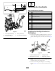
Form No. 3399-289 Rev A CE Light Kit Groundsmaster® 4500-D, 4700-D, or Reelmaster® 7000-D Traction Unit Model No. 31573 Installation Instructions WARNING CALIFORNIA Proposition 65 Warning This product contains a chemical or chemicals known to the State of California to cause cancer, birth defects, or reproductive harm. Installation Loose Parts Use the chart below to verify that all parts have been shipped.
Procedure Description 1 1 1 1 1 1 1 1 1 2 1 1 2 2 1 1 1 1 1 2 1 2 2 4 1 2 1 1 4 4 2 2 1 1 3 3 11 3 1 1 Column bracket Flasher module On-Off-On rocker switch Beacon switch Paddle switch Horn switch Horn button Horn decal (Part No.
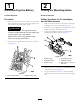
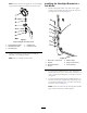
1 2 Disconnecting the Battery Drilling the Mounting Holes No Parts Required No Parts Required Procedure Drilling the Holes for the Headlights and the Wire Harness 1. Move the traction unit to a level surface, set the parking brake, lower the cutting units, shut off the engine, and remove the key from the ignition switch. 1. Remove the nuts from the 2 carriage bolts securing the headlights to the traction-unit frame (Figure 2). 2.
Figure 3 1. 6.4 cm (2-1/2 inches) 4. 1.0 cm (13/32 inch) diameter 2. 8.9 cm (3-1/2 inches) 5. 1.9 cm (3/4 inch) 3. 14.0 cm (5-1/2 inches) Drilling the Holes for the Horn Bracket Drilling the Holes in the Front Footrest for the Brake-Pedal Switch Using the dimensions in Figure 4, locate and drill 2 holes (7 mm) through both walls of the roller-support tube. Using the dimensions in Figure 5, locate and drill 2 holes (7 mm) through the front footrest. Figure 4 1. 1.9 cm (3/4 inch) 3. 25.
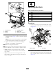
3 Installing the Headlights Parts needed for this procedure: 1. 15.5 cm (6-7/64 inches) 4. 17 mm (11/16 inch) 5. 7 mm (9/32 inch) diameter Right headlight bracket 1 Left headlight bracket 6 Bolt (3/8 x 2-1/2 inches) 6 Flange nut (3/8 inch) 8 Washer (3/8 x 7/8 inches) 2 Rubber hanger 4 Spacer 4 Bolt (5/16 x 1-5/8 inches) 4 Flange nut (5/16 inch) 1 Right headlight assembly 1 Left headlight assembly 2 Bent-plate bracket Installing the Headlight Bracket to a ROPS Model Figure 5 2.
Installing the Headlight Bracket to a Cab Model Note: Ensure that the turn-signal lens on the headlight is positioned toward the outside of the traction unit. 1. Install a bent-plate bracket onto each of the upper corners of the lower front panel of the cab with the existing screws as shown in Figure 8. Figure 7 Right headlight assembly shown 1. Right headlight bracket 4. Headlight arm 2. Articulated-joint shell 5. Locknut (10 mm) 3. Articulated joint 3.
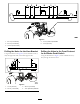
4 Installing the Horn Parts needed for this procedure: 1 Horn 1 Horn bracket 1 Bolt (3/8 x 5/8 inch) 1 Flange nut (3/8 inch) 2 Bolt (1/4 x 2 inches) 2 Nut (1/4 inch) Procedure 1. Secure the horn strap to the horn bracket with a bolt (3/8 x 5/8 inch) and a flange nut (3/8 inch) as shown in Figure 10. Figure 9 1. Nut (5/16 inch) 4. Headlight bracket 2. Washer 3. Spacer 5. Bracket tab 6. Bolt (5/16 x 1-5/8 inch) 4.
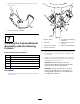
5 6 Installing the Relay Switch Installing the Flasher Module and Switches on the Column Bracket Parts needed for this procedure: 1 Relay switch 1 Serrated hex-head flange bolt (#8 x 1/2 inch) 1 Locknut (#8) Parts needed for this procedure: 1 Column bracket 1 Flasher module Procedure 1 On-Off-On rocker switch Secure the relay switch under the battery cover with a serrated hex-head flange bolt (#8 x 1/2 inch) and a locknut (#8) at the location shown in Figure 11.
2. Install the horn decal (Part No. 104-6957) as shown in Figure 13. Figure 13 1. Horn decal (Part No. 104-6957) 7 Figure 14 1. Steering column 2. Foam strip Installing the Column-Bracket Assembly onto the Steering Column 3. Column mount bracket Steering-column bracket 1 Column mount bracket 2 Carriage bolt (3/8 x 3/4 inch) 2 Flange nut (3/8 inch) 1 Foam strip 1 Cable tie 7. Column-bracket assembly 4. Locknut—3/8 inch (2) 2.
8 Installing Brake-Sensor Bracket Parts needed for this procedure: 1 Carriage bolt (#10 x 5/8 inch) 1 Locknut (#10) 1 Sensor plate 2 Flange nut (1/4 inch) 1 Brake-sensor bracket 2 Bolts (1/4 x 3/4 inch) 2 Slotted screw (#6 x 1 inch) 4 Washer (#6) 1 Brake sensor 2 Locknut (#6) Procedure 1. Disassemble the proximity-sensor assembly on the brake-pedal lever (Figure 15) and set aside all the parts except the proximity sensor. Figure 15 1. Forward footrest 4. Proximity sensor 2.
lights when the brake pedal is pressed. Realign the brake sensor if necessary. 9 Installing the Rear Lamps Parts needed for this procedure: 1 Left light bracket 1 Right light bracket 4 Screw (5/8 x 3 inches) 4 Flat washer 2 Jam nut (5/8 inch) 2 Rear-lamp assembly Procedure 1. Remove the 2 bolts, 2 washers, and 2 nuts securing the reservoir-mounting bracket to the left frame rail (Figure 17). Note: Stabilize the reservoir and bracket to prevent them from falling. Figure 16 5.
10 2 1 Installing the Wire Harness Parts needed for this procedure: 3 3 3 Wire harness 1 Switch-panel-enclosure cover 3 Screw (#10 x 1/2 inch) 3 Mounting pad 11 Cable tie Procedure G023194 Figure 18 1. Left light bracket 1 Use the following instructions and illustrations to route and connect the wire harness. 3. Rear lamp 2. Right light bracket 3. Mount the rear lamp to light bracket with the bolts and nuts included with the light (Figure 18).
1 1 2 2 3 4 G023200 Figure 23 G023198 Figure 21 1. Compartment clamp 1. Self-tapping screws (#8 x 1/2 inch) 3. Junction block 2. Ground-block terminal 4. Wire harness fuse block 2. Seal 5. Connect the large-ring terminal, from the wire harness, to the stud on the junction block (Figure 23). 2. From under the right side of the traction unit, route the fuse-block section of the wire harness up to and into the opening in the fuse compartment (Figure 22). 6.
Figure 25 2. Headlight 4. Washer-head screws and nuts 5. Headlight wire connectors 3. Carriage bolt and nut 6. Hole for wire harness 1. Platform shroud Figure 27 1. Cover 2. Hex socket button-head screws 12. Secure the shroud and the headlights to the frame with the 2 carriage bolts and nuts you previously removed (Figure 25). 16. Secure the wire harness to the column using the cable tie inserted into the slots in the column mount bracket; refer to Figure 14. 13.
Figure 30 Figure 29 1. Fuse (10 A) 3. Fuse (10 A) 2. Fuse (10 A) 4. Fuse (15 A) 2. Install the fuse-box decal to the storage-box cover (Figure 31). 20. Plug the wire-harness connector into the light connector. 21. Route the wire harness to the registration-plate light and plug the wire-harness connector into the light connector, if applicable (Figure 29). Important: Secure the wire harness with cable ties so that it does not contact any hot or moving parts. 22.
Operation 12 Controls Connecting the Battery Hazard Switch Press the hazard switch (Figure 33) to the ON position to activate the front and rear flashing hazard lights. No Parts Required Procedure Connect the negative battery cable to the battery post (Figure 32). Figure 33 Figure 32 1. Positive battery cable 1. Turn signal switch 3. Hazard switch 2. Horn button 4. Beacon switch (optional) 2.
4. Mount a magnetic protractor onto the plate. 5. While holding the assembly in place, carefully tilt the headlight downward 3 degrees, then tighten the nut. 6. Repeat the procedure for the other headlight.
Notes: 18
Notes: 19