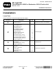
Form No. 3423-501 Rev B EU Light Kit Groundsmaster® 4300-D or Reelmaster® 5010-H Traction Unit Model No. 31579 Installation Instructions Installation Loose Parts Use the chart below to verify that all parts have been shipped.
Procedure 5 6 7 Description 1 1 1 1 1 1 1 1 2 1 2 2 1 1 1 2 1 2 2 2 2 3 1 1 1 2 Column mount bracket Flasher module On-Off-On rocker switch Beacon switch Paddle switch Horn switch Horn button Hex socket button-head screw Speed nut Steering-column bracket Carriage bolt (3/8 x 1inch) Flange nut (3/8 inch) Wire harness Adapter harness (long) Tie clip Adapter harness (short) Fuse block mount Flange nut (5/16 inch) Locknut (M6) Flange bolt (M6) Flange bolt (5/16 x 1 inch) Sign Serial plate Speed plate U-bo
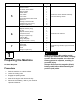
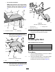
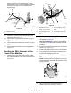
2 Installing the Lights Parts needed for this procedure: 1 Right headlight mount 1 Left headlight mount 1 Right tail light mount 1 Left tail light mount 1 Right headlight assembly 1 Left headlight assembly 2 Tail light assembly 2 Tail light extension bracket 10 Flange nut (3/8 inch) 1 Hex-head bolt (3/8 x 1 inch) 2. Remove the shroud from the frame. 4 Hex-head bolt (5/16 x 1 inch) 3.
headlight mount to the right floor bracket (Figure 2). 5. Fasten the left and right headlights to the headlight mounts (Figure 3) with the fasteners supplied with the lights. Note: Ensure that the turn-signal lens on the headlight is positioned toward the outside of the traction unit. g238255 Figure 4 Left side of the machine shown 1. Bolt 2. Rear of the machine B. Use the previously removed bolts to secure the tail light extension brackets to the frame rail (Figure 5).
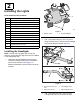
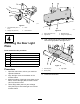
• For all other machines: Note: Older machines may have a chassis leg that extends in front of the radiator-frame fasteners. Remove the chassis leg, then file and paint over the new chassis end (Figure 6). g239132 Figure 8 Left side of the machine shown 1. Nut (5/16 inch) 3. Tail light mount 2. Bolt (5/16 x 3/4 inch) g260849 Figure 6 1. Cut location—chassis A. 3. 2. Chassis leg Remove the existing fasteners from both sides of the radiator frame near the machine frame rail (Figure 7).
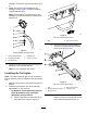
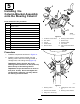
g238169 Figure 9 1. Hex-head bolt (3/8 x 1 inch) 3. Horn 2. Flange nut (3/8 inch) 4. Horn bracket g237977 Figure 10 4 1. Flange bolt (3/8 inch) 3. Machine frame 2. Light mount 4. Flange nut (3/8 inch) 5. Use 2 screws (#10) and 2 locknuts (#10) to secure the light plate to the light mount. Installing the Rear Light Plate Parts needed for this procedure: 1 Light mount 1 Light plate 2 Flange nut (3/8 inch) 2 Locknut (#10) 2 Flange bolt (3/8 inch) 2 Screw (#10) g237978 Figure 11 1.
5 Installing the Column-Bracket Assembly onto the Steering Column Parts needed for this procedure: 1 Column mount bracket 1 Flasher module 1 On-Off-On rocker switch 1 Beacon switch 1 Paddle switch 1 Horn switch g034342 Figure 12 1 Horn button 1 Hex socket button-head screw 1. On-Off-On rocker switch 6. Steering-column bracket Speed nut 2. Horn button 7. Speed nut (2) 2 1 Steering-column bracket 2 Carriage bolt (3/8 x 1inch) 2 Flange nut (3/8 inch) 3. Locknut 4. Paddle switch 5.
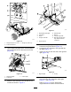
6 Installing the Wire Harness Parts needed for this procedure: 1 Wire harness 1 Adapter harness (long) 1 Tie clip 2 Adapter harness (short) 1 Fuse block mount 2 Flange nut (5/16 inch) 2 Locknut (M6) 2 Flange bolt (M6) 2 Flange bolt (5/16 x 1 inch) g253589 Figure 14 Wire harness overview 1. Registration plate lights 9. Shroud headlight—right side 10. Horn 11. Kit headlight—right side Wire Harness Overview 2. Fuse block 3.
g253588 Figure 17 1. Registration plate lights 6. Neutral switch 2. Fuse block 3. Starter 7. Beacon 8. Tail light—right side 4. Tail light—left side 9. Main wire harness and long adapter harness connection g238193 Figure 15 1. Flange bolt (5/16 x 1 inch) 5. Engine ground 3. Flange nut (5/16 inch) 2. Fuse block bracket 5. 3. 6. Use 2 flange bolts (M6) and 2 locknuts (M6) to secure the fuse block to the fuse block mount (Figure 16). 7.
Place 1 magnet on the inside surface of the license plate mount. Route the adapter harness through the tie clip that you installed in the previous step. g238237 Figure 20 g253614 Figure 19 1. Registration plate light 3. Tie clip 2. Magnet tie mount 9. Continue to route the wire harness along the right frame rail (Figure 17). 10. Connect the ring terminal to the starter (Figure 17). 11. Connect the wire harness to the beacon (Figure 17). 12.
8. Route the wire harness to the column-bracket assembly on the steering column (Figure 20). 9. Plug the connectors into the flasher module, horn, turn signal, and hazard switches (Figure 22). 7 Installing the Signs and Serial Plate Parts needed for this procedure: 3 Sign 1 Serial plate 1 Speed plate 1 U-bolt 2 Flange nut (3/8 inch) Procedure g034567 1. Figure 22 10. Adhere a sign on both sides of the machine (Figure 24).
8 Connecting the Battery No Parts Required Procedure Connect the battery; refer to your machine Operator’s Manual. WARNING Incorrect battery cable routing could damage the sprayer and cables, causing sparks. Electrical sparks can cause the battery gasses to explode, resulting in personal injury. Always connect the positive (red) battery cable before connecting the negative (black) cable. g238047 Figure 25 1. Serial plate 3. 14.9 cm (5-3/4 inches) 2. Stamp the serial number here. 4. 1.
Aiming the Headlights Operation Controls g034583 Figure 26 1. Turn signal switch 3. Hazard switch 2. Horn button 4. Beacon switch (optional) Hazard Switch Press the hazard switch (Figure 26) to the ON position to activate the front and rear flashing hazard lights. Turn-Signal Switch Press down on the left side of the turn-signal switch (Figure 26) to activate the left-turn signal. The center position is off.
Notes:
Notes: