Form No. 3369-329 Rev A Light Kit Groundsmaster® 5900 Series Rotary Mower Model No. 31582 Installation Instructions Installation Loose Parts Use the chart below to verify that all parts have been shipped. Procedure Description 1 2 3 4 5 6 Use Qty. No parts required – Flasher bracket Flange head screw, 1/4 x 1/2 inch Flange nut, 1/4 inch Flasher module Wire harness Switch, hazard Cable tie Headlamp bracket, L.H. (for model without cab) Headlamp bracket, R.H.
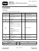
1 Disconnecting the Battery No Parts Required Procedure 1. Position the machine on a level surface, set the parking brake, lower the cutting units, turn the ignition off, and remove the key. Figure 1 CAUTION 1. Steering tower cover If you leave the key in the ignition switch, someone could accidently start the engine and seriously injure you or bystanders. 2. Mounting screw 2. Mount the flasher module to the bracket with a #10 x 5/8 inch screw (2) .216 x .
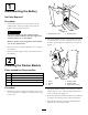
Figure 3 3
3 4 Installing the Hazard Switch Installing the Headlights Parts needed for this procedure: Parts needed for this procedure: 1 Switch, hazard 1 Headlamp bracket, L.H. (for model without cab) 2 Cable tie 1 Headlamp bracket, R.H. (for model without cab) 1 Headlamp bracket, R.H. (for model with cab) 1 Headlamp bracket, L.H. (for model with cab) 1 Headlamp R.H. 1 Headlamp L.H.
. Route the headlight wire harness ends underneath the front edge of the operator’s platform, thru the headlight brackets and to the headlights (Figure 3). 6. Plug one of the harness connectors into the previously unplugged harness connector and one into the headlight. The headlight connection should be made inside the headlight bracket. Repeat this procedure on the other headlight. 7. Using the hole in each headlight bracket, secure the harness, to the bracket with a cable tie as shown in Figure 7. 8.
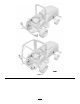
Figure 9 1. Flange head bolt, 1/4 x 3/4 inch 2. Cab bracket 3. Flange nut, 1/2 inch 4. Headlight assembly, L.H. 5. Flange nut, 1/4 inch Figure 10 6. Cable ties 7. Headlight bracket, L.H. 8. Flange head bolt, 1/2 x 1-1/4 inch 1. Headlight assembly, R.H. 2. Headlight bracket, R.H. 3. Flange head bolt, 1/4 x 3/4 inch 4. Cab bracket 4. Loosely mount the end of the headlight bracket to the side of the cab bracket with a 1/4 x 3/4 inch flange head bolt and 1/4 inch flange nut (Figure 9). 5.
5 Installing the Fuse Block Parts needed for this procedure: 1 Fuse, 10 amp 1 Fuse block 1 Decal, turn signal fuse Procedure 1. Affix and connect the new fuse block to the existing fuse blocks (Figure 11). This may not necessary if a new fuse block was previously installed for another attachment. Note: The (2) screws and nuts from the adjoining fuse block may be removed and reused to secure the new fuse block to the machine. 2. Insert the 10 amp fuse into the open slot on the fuse block (Figure 11).
Figure 13 1. Rear bumper bracket bolts and nuts Figure 15 2. Using the bolts and nuts previously removed, secure a lamp assembly to the bracket and frame (Figure 14). 1. Hood support bracket 2. Valve 3. Radiator support 1 2 • Affix a cable tie mounting pad to the under side of the frame, behind the rear axle and approximately 7 inches (17.8 cm) from the right frame rail (Figure 16). 5 Important: Make sure the mounting surface is cleaned with rubbing alcohol before installing the mounting pad.
• Along the existing hard line to the radiator support (Figure 17). Figure 17 1. Hood support frame 2. Corner shroud 3. Muffler heat shield 4. Radiator support • Over the hard lines down through the frame (Figure 17). • Affix a cable tie mounting pad to the under side of the frame, behind the rear axle and approximately 7 inches (17.8 cm) from the left frame rail (Figure 16). Figure 16 1. At least 7 inches (17.8 cm) 2. Cable tie mounting pad • Secure the harness to the mounting pad with a cable tie.
Operation 7 Connecting the Battery Using the Light and Hazard Switches No Parts Required • Turn the key switch ON and press the light switch to the ON position to activate the head lamps. Procedure • Press the hazard switch to the On position to activate the front and rear flashing hazard lights. 1. Connect the negative battery cable to both batteries.
Schematics Electrical Schematic (Rev.