Form No. 3444-722 Rev C EU Light Kit Groundsmaster® 4000 Series Rotary Mower Model No. 31694 Installation Instructions This product complies with all relevant European directives. For details, please see the Declaration of Incorporation (DOI) at the back of this publication. Safety Safety and Instructional Decals Safety decals and instructions are easily visible to the operator and are located near any area of potential danger. Replace any decal that is damaged or missing. decal140-1623 140-1623 1.
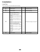
Installation Loose Parts Use the chart below to verify that all parts have been shipped. Procedure 1 2 3 4 Description Qty. Use No parts required – Prepare the machine. No parts required – Disconnect the battery. Right headlight—Part No. 140-6772 (light, mount, washer, and nut) Left headlight—Part No.
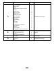
Procedure 5 6 7 8 Description Qty.
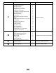
Procedure 9 10 11 12 Description Qty.
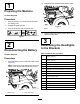
2. 1 Disconnect the negative (black) battery cable. Preparing the Machine No Parts Required Procedure 1. Park the machine on a level surface and lower the cutting units. 2. Engage the parking brake. 3. Shut off the engine and remove the key. g020451 Figure 3 1. Battery 3. Slip the rubber boot off the positive terminal, and disconnect the cable.
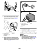
Identifying the Headlights At the bracket side of the headlight, look at the information printed on the housing (Figure 4). Note the part number and the “RH” or “LH” information. g350858 Figure 7 Machines with a Cab 2. Right light mount 1. Left light mount g350385 Figure 4 Removing the Floor Panel Hardware Identifying the Headlight Mounts Machines with a Roll Bar Use Figure 5, Figure 6, and Figure 7 to identify the headlight mounts for your machine.
2. Assembling the Headlights Assemble the capscrew (12 mm) to the light mount for the Groundsmaster 4000 machines (Figure 9) with the locknut (12 mm) and lock washer (12 mm). Groundsmaster 4100 Machines Important: Ensure that you assemble the headlight marked left and the left light mount, and the headlight marked right and the right light mount. 1. If assembled, remove the locknut (12 mm) and lock washer (12 mm) from the capscrew in the headlight bracket. 2.
g350619 Figure 13 1. Grommet 4. Figure 12 Right headlight shown. 3. Lock washer 2. Light mount (machines with a cab) 4. Locknut 3. Repeat steps 1 through 3 for the other headlight and light mount. 4 g350618 1. Headlight 2. Cab headlight bracket Installing the Headlights No Parts Required Installing the Headlights and Light Mounts Assemble the grommet to the 38 mm (1-1/2 inch) hole in the light mount (Figure 13). Machines with a Roll Bar 1.
g350746 Figure 15 Groundsmaster 4100 Machines g350744 Figure 14 Groundsmaster 4000 Machines 1. Capscrew (1/2 x 4-1/2 inches) 4. Front frame 2. Thin washer (1/2 x 1-3/8 inch) 5. Thick washer (1/2 x 2-1/4 x 3/8 inch) 3. Headlight and light mount(Groundsmaster 4000 machines) 6. Flange locknut (1/2 inch) 9 1. Capscrew (1/2 x 4-1/2 inches) 4. Front frame 2. Thin washer (1/2 x 1-3/8 inch) 5. Thick washer (1/2 x 2-1/4 x 3/8 inch) 3. Headlight and light mount (Groundsmaster 4000 machines) 6.
g350888 Figure 16 Groundsmaster 4000 shown; the Groundsmaster 4100 is similar. 4. For Groundsmaster 4000 machines, route the 6-socket connector (labeled HEADLIGHT LH or HEADLIGHT RH of the machine wire harness through the grommet as shown in Figure 17. g350820 Figure 18 1. 6-socket connector (labeled HEADLIGHT LH or HEADLIGHT RH—machine wire harness) 3. Headlight 2. Cap 6. Bundle the excess wire harness and secure it to the chassis with a cable tie. 7.
g350904 Figure 21 1. 6-socket connector (labeled HEADLIGHT LH or HEADLIGHT RH—machine wire harness) g350620 Figure 19 1. Cab headlight bracket 4. Flange locknut (1/2 inch) 2. Flange-head capscrew (1/2 x 1 inch) 5. Carriage bolt (1/4 x 5/8 inch) 3. Headlight bracket 6. Flange locknut (1/4 inch) 2. Tighten the locknut and carriage bolt. 3. Torque locknut and capscrew and locknut to 91 to 113 N∙m (67 to 83 ft-lb). 4.
5 Installing the Control Console Parts needed for this procedure: g350820 Figure 22 1. 6-socket connector (labeled HEADLIGHT LH or HEADLIGHT RH—machine wire harness) 3. Headlight 2. Cap 6. Repeat steps 1 through 3 for the headlight and light mount at the other side of the machine.
g350969 Figure 23 1. Boot 3. Steering cover 2. Flange-head screws 2. Remove the 4 flange-head screws that secure the steering cover to the cover mounts, and lift the cover (Figure 23). 3. Grind a notch in the steering cover as show in Figure 24. g350970 Figure 25 1. 12-pin connector (control harness) 2. Notch (steering cover) 5. Assemble the steering cover to the cover mounts with the 4 flange-head screws. 6. Pull the boot down and assemble the bottom of it into the steering cover (Figure 26).
Assembling the Fuse Mount Plate 1. Assemble the clip nut (#10) onto the fuse mount plate (Figure 27). g350765 Figure 28 1. 12-pin connector (flasher) 5. g350763 Figure 27 1. Clip nut (#10) 4. Flange head screw (#10 x 3/8 inch) 2. Fuse mount plate 5. Cable tie 3. Flasher 2. Assemble the flasher to the mount plate (Figure 27) with a flange head screw (#10 x 3/8 inch). 3. Secure the flasher to the mount plate with a cable tie (Figure 27). 4.
g350766 Figure 29 1. Bracket mount 2. Push-in anchor (console harness) g350767 Assembling the Switch Mount 1. Figure 30 1. Switch mount Assemble the 8 clip nut (1/4 inch) to the switch mount as shown in Figure 30. 2. 2. Clip nut (1/4 inch) Insert the multi-function switch into the 100 mm (2 inch) hole in the switch mount as shown in Figure 31. g350769 Figure 31 1. Switch mount 15 2.
3. Secure the multi-function switch to the switch mount with the thick and thin switch clips (Figure 32). g350778 Figure 32 1. Tab (multi-function switch) g350768 Figure 34 3. Switch clip (thin) 2. Switch clip (thick) 1. Rocker switch 4. 6. Insert the 3 switch plugs into the switch mount as shown in Figure 33. 2. Front of the switch plate Assemble the 2 knobs into the fuse cover, and secure the knobs with 2 bolt retainers (Figure 35). g350764 Figure 35 1. Bolt retainer 2. Fuse cover 3.
Installing the Switch Plate to the Steering Column 1. Align the switch plate to the rearward side or the steering column (Figure 37). g350772 Figure 37 1. Bracket mount 4. Fuse mount plate 2. Carriage bolt (1/4 x 2 inches) 5. Flange locknut (1/4 inch) 3. Switch mount 4. At the lower 6.4 mm (1/4 inch) holes, assemble 2 carriage bolts bolt (1/4 x 2 inches) through the switch plate, bracket mount, and fuse mount plate (Figure 37) with 2 carriage bolts (1/4 x 2 inches) and 2 flange locknuts (1/4 inch).
2. Plug the 9-pin connector of the multi-function switch harness into the 9-socket connector of the console harness (Figure 39). g350771 Figure 41 1. Flange-heads screw (1/4 x 3/4 inch) 2. Control cover g350777 Figure 39 1. 9-pin connector (multi-function switch harness) 3. 2. 9-socket connector (console harness) 6 Secure the console harness to the steering column with 2 cable ties. Installing the Horn and Connecting the Console Harness Installing the Control Cover 1.
g351028 Figure 42 g351026 Figure 44 1. Horn 2. Spade-socket connector 4. 3. Cable tie Secure the horn wires with a cable tie. Connecting the Harness 1. Remove the cap from the 12-socket connector of the machine wire harness (Figure 45). g351025 Figure 43 1. Horn and bracket 4. Capscrew (5/16 x 3/4 inch) 2. Flange locknut (5/16 inch) 5. Right side of the machine 3. Column brace 2.
2. Plug the 12-pin connector of the console harness into the 12-socket connector of the machine wire harness (Figure 45). 3. Clean the right support channel below the operator’s platform, and allow the channel to dry (Figure 47 and Figure 48). 7 Installing the Identity Plate Machines Operated in Germany Parts needed for this procedure: 1 Tape (double-face adhesive) 1 Identity plate g350944 Figure 47 Procedure 1. Remove the backing from the double-face adhesive tape (Figure 46).
Removing the Electrical Cover 8 Machines with a Cab At the floor along right side of the operator’s seat, remove the 2 socket-head screws that secure the controller cover to the electrical-component mount, and remove the cover (Figure 50).
g351093 g351013 Figure 53 Figure 51 1. Electrical cover 2. Socket-head screw 1. Fuse (10 A) and fuse-block 3. Fuse (15 A) and fuse-block slot A3 slot A4 2. Fuse (10 A) and fuse-block slot D4 2. 2. Plug the horn relay into the 4-socket connector of the machine wire harness as shown in Figure 52. 3. Washer 4.
9 Installing the Taillights Parts needed for this procedure: 1 Left light housing 1 Left light-housing mount 1 Right light housing 1 Right light-housing mount 4 Carriage bolt (1/4 x 5/8 inch) 4 Flange locknut (1/4 inch) 1 Left taillight and license plate harness 1 Right taillight harness 4 Clip nut (1/4 inch) 2. Left light-housing mount 5. Right light housing 2 Inner mount 6. Right light-housing mount 8 Socket-head screw (1/4 x 3/4 inch) 3.
g350574 Figure 57 g351322 1. Inner mount 3. Light housing 2. Clip nut (1/4 inch) 4. Socket-head screw (1/4 x 3/4 inch) 4. Align the 4-socket connector of the harness through the inner mount (Figure 57). 5. Assemble the inner mount into the light housing, and secure the mount to the housing (Figure 57) with 4 socket-head screws (1/4 x 3/4 inch). 6. Repeat steps 3 through 5 for the other inner mount and light housing. Figure 56 1. Left light housing 4. Right light housing 2.
Assembling the Taillights 1. Align the taillight to the light housing with the yellow lens positioned as shown in Figure 58. g351422 Figure 59 1. Capscrew (1/4 x 3/4 inch) 3. Pivot bracket 2. Light-housing mount 4. Locknut (1/4 inch) 6. Install the mount cover to the light-housing mount with 4 push-in fasteners (Figure 60). g350575 Figure 58 1. Yellow lens (taillight) 4. Phillips-head screw (#10 x 1-1/4 inches) 2. Red lens (taillight) 5. Clip nut (#10) 3.
g350605 Figure 62 1. Carriage bolt (3/8 x 1-1/4 inches) 3. Flange locknut (3/8 inch) 2. Pivot bracket 6. 10 g350534 Figure 61 1. Flange locknut (1/2 inch) 4. Carriage bolt (1/4 x 1-1/4 inches) 2. Washer (1/2 inch) 5. Swivel-adapter mount Installing the License Plate and Side Decals 3. Capscrew (1/2 x 1-1/4 inches) 2. 3. 4. 5. Repeat steps 1 through 4 for the swivel-adapter mount at the other side of the bumper.
g350747 Figure 63 1. Bumper 2. Spacer 4. Slow moving vehicle mount 5. Speed decal g350775 Figure 64 3. Flange-head locknut (1/4 inch) 1. Nut clip (#10) 3. Socket-head screws (#10 x 3/4 inch) 2. License-plate light 2. Remove the backing film from the speed decal. 3. Align the speed decal to the slow moving vehicle mount, and adhere the decal to the mount (Figure 63). 5. Align the harness of the license-plate light through the slow moving vehicle mount (Figure 64). 4.
4. Torque the capscrews to 37 to 45 N∙m (27 to 33 ft-lb). Installing the Speed Decals to the Hood 1. Clean the side of the hood at the decal placement area shown in Figure 67, and allow the hood to dry. g351162 g351163 Figure 65 g351175 1. Hood pivot bracket 2. Flange-head capscrew (3/8 x 1-1/4 inches) Figure 67 1. 29 cm (11-1/2 inches) 2. Align the holes on the slow moving vehicle mount with the slots in the hood pivot bracket (Figure 66). 2. 2. 7.
5. 11 At the inboard side of the frame rail, remove the cap from the 4-socket connector labeled LH REAR LIGHT of the machine wire harness (Figure 70). Connecting the Taillight Harnesses No Parts Required Routing and Connecting the Left Taillight 1. Unlatch and open the hood. 2. Route the 4-socket connector labeled LH REAR LIGHT of the machine wire harness under the left frame rail and forward (Figure 69). g350866 Figure 70 1.
Routing and Connecting the Right Taillight 1. Route the 4-socket connector labeled RH REAR LIGHT of the machine wire harness under the left frame rail and forward (Figure 73). g351443 Figure 71 1. Push-in anchor 3. Cap 2. Hole (hood-hinge mount—left) 4. 2-socket connector (license-plate light branch—left taillight harness) g351427 2. Remove the cap from the 2-socket connector of the license-plate light wiring branch (Figure 75). 3.
g020451 Figure 75 1. Battery g350907 2. Connect the negative (black) battery cable. 3. Close the battery compartment cover (Figure 76) until it securely snaps shut. Figure 74 1. Cap 3. 4-pin connector (labeled RH Rear Lights—right taillight harness) 2. 4-socket connector (labeled RH REAR LIGHT—machine wire harness) 3. Plug the 4-pin connector labeled RH Rear Lights of right taillight harness into the 4-socket connector labeled RH REAR LIGHT of the machine wire harness (Figure 70).
Operation 1. Turn the key switch on and press the light switch to the ON position. Controls 2. Rotate the light switch (Figure 77 and Figure 78) to the following positions: Note: Check the operation of the lights. Make sure • OFF that the correct lights are flashing when operating the turn signal switch. • Road lights ON • Road lights and optional work light ON Using the Turn Signal • Move the turn signal switch (Figure 77) up to signal a right turn. • Move the switch down to signal a left turn.
Maintenance Adjusting the Headlights 1. Loosen the mounting locknuts and capscrews to adjust the lights (Figure 76). Servicing the Fuses Replacing a Fuse Block Fuse 1. Park the machine on a level surface, engage the parking brake, lower the cutting units, shut off the engine, and remove the key. 2. Remove the electrical cover, refer to Removing the Electrical Cover (page 21) or Removing the Electrical Cover (page 21). 3. Replace the open fuse. g351458 Figure 80 1.
g350865 Figure 82 1. Cap 3. In-line fuse holder 2. Fuse 4. Replace the fuse; refer to the Fuse Table. Fuse Table Left taillight harness Protected Circuits Fuse Rating Labeled LH REAR LIGHTS (left taillight harness) Taillights and license plate light 5A Labeled BRAKE LIGHT FUSE Brake lights 5A Left taillight harness Protected Circuits Fuse Rating Labeled RH REAR LIGHTS (right taillight harness) Taillights and license plate light 5A Labeled BRAKE LIGHT FUSE Brake lights 5A 5.
Declaration of Incorporation The Toro Company, 8111 Lyndale Avenue South, Bloomington, MN, USA declares that the following unit(s) conform(s) to the directives listed, when installed in accordance with the accompanying instructions onto certain Toro models as indicated on the relevant Declarations of Conformity. Model No. 31694 Serial No.