
Installation Instructions


g350969
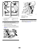
Figure23
1.Boot
3.Steeringcover
2.Flange-headscrews
2.Removethe4ange-headscrewsthatsecure
thesteeringcovertothecovermounts,andlift
thecover(Figure23).
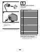
3.Grindanotchinthesteeringcoverasshowin
Figure24.
g350968
Figure24
1.Notch(steeringcover)3.11mm(7/16inch)
2.6mm(1/4inch)
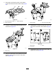
4.Alignthe12-pinconnectorendofthecontrol
harnessthroughnotchinthesteeringcover
(Figure25).
g350970
Figure25
1.12-pinconnector(control
harness)
2.Notch(steeringcover)
5.Assemblethesteeringcovertothecovermounts
withthe4ange-headscrews.
6.Pullthebootdownandassemblethebottomof
itintothesteeringcover(Figure26).
g350967
Figure26
13