Form No. 3444-734 Rev A EU Light Kit Groundsmaster® 5900 Series Rotary Mower with Cab Model No. 31695 Installation Instructions This product complies with all relevant European directives. For details, please see the Declaration of Incorporation (DOI) at the back of this publication. Safety Safety and Instructional Decals Safety decals and instructions are easily visible to the operator and are located near any area of potential danger. Replace any decal that is damaged or missing.
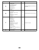
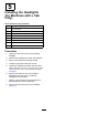
Procedure 5 6 7 8 Description Qty.
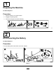
1 Preparing the Machine No Parts Required Procedure 1. Park the machine on a level surface. 2. Engage the parking brake. 3. Shut off the engine and remove the key. g038719 Figure 1 2 Disconnecting the Battery No Parts Required Procedure Turn the battery-disconnect switch to the OFF position.
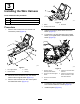
3 Installing the Wire Harness Parts needed for this procedure: 1 Wire harness 1 Switch 1 Auxiliary-brake decal g186717 Figure 4 Procedure 1. 3. Knockout 1. Switch 2. Auxiliary-brake decal Remove the 6 bolts from the console and remove the panel (Figure 3). 4. Adhere the auxiliary-brake decal above the switch (Figure 4). 5. Connect the new wire harness to the hazard switch, turn-signal switch, and auxiliary-brake switch (Figure 5). g186692 Figure 3 1. Turn-signal switch 3. Panel 2.
4 Installing the Headlights (for Machines with ROPS only) Parts needed for this procedure: 1 Right light bracket 1 Left light bracket 2 Grommet 2. Remove the headlights and retain lights and hardware. 3. Remove the brackets from the headlights and discard the brackets (Figure 6). 4. Using the fasteners that you removed, install the left and right light brackets to the existing holes in the front of the operator’s platform (Figure 6). 5.
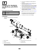
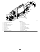
5 Installing the Headlights (for Machines with a Cab Only) Parts needed for this procedure: 1 Right light bracket 1 Left light bracket 1 Right headlight assembly 1 Left headlight assembly 2 Bolt (1/2 x 1 inch) 2 Nut (1/2 inch) 2 Bolt (1/4 x 3/4 inch) 2 Nut (1/4 inch) 2 Grommet Procedure 1. Unplug the wire harness from each existing headlight. 2. Remove the headlights and retain the hardware. 3. Remove and discard the existing bracket. 4. Install the grommets to the light mounts. 5.
g349447 Figure 7 1. Headlight 6. Left headlight mount 2. Grommet 7. Bolt (1/4 x 3/4 inch) 3. Wire harness 8. Remove and discard the existing bracket. 4. Bolt (1/2 x 1 inch) 9. Nut (1/2 inch) 5. Nut (1/4 inch) 10.
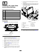
6 7. Route the wire to the plate light and connect it to the light. 8. Install the plate light to the license bracket using 2 screws (#10 x 3/4 inch) and the speed nuts in the license bracket. Installing the Light Plate and License Bracket Parts needed for this procedure: 1 Plate light 1 License bracket 1 Sign mount 2 Screw Screw (#10 x 3/4 inch) 2 Speed nut 2 Carriage bolt (1/4 x 5/8 inch) 2 Nut (1/4 inch) Decal (20) Procedure 1.
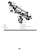
2. Remove the tail lights from the machine. 3. Remove the brackets from the rear bumper and discard the brackets and hardware (Figure 10). Installing the Rear Lights 4. Remove the bottom 2 bolts (1/2 x 1-1/4 inch), on each side, that secure the bumper to the machine frame. Parts needed for this procedure: 5. Install a pivot bracket to each side of the machine with 2 bolts (1/2 x 1-1/2 inch); refer to Figure 10. 6.
g349462 Figure 10 1. Hex-socket button head screw 10. Left housing 2. Inner mount 3. Existing light (yellow lens on top) 11. Left tube mount 12. Carriage bolt (5/16 x 3/4 inch) 4. Existing phillips-head screw 13. Light mount 5. Nut (1/4 inch) 14. Right mount tube 6. Nut (5/16 inch) 15. Remove the existing lights. 7. Bolt (1/4 x 3/4 inch) 16. Remove the existing brackets. 8. Pivot bracket 17. Right housing 9. Carriage bolt (1/4 x 5/8 inch) 18.
Operation 8 Using the Light and Hazard Switches Verifying that the Machine is in CE Mode • Turn the key switch on and press the light switch to the ON position to activate the head lamps. No Parts Required • Press the hazard switch to the ON position to Procedure • Turn the key switch on and press the left side of activate the front and rear flashing hazard lights. 1. Start the machine. 2. From the InfoCenter main menu, navigate to the About screen (Figure 11).
Using the Auxiliary-Brake Switch Press and hold the auxiliary-brake switch to decrease the engine speed (Figure 12); release the switch to stop the deceleration and remain at the current engine speed. Note: You may use the switch intermittently to gradually slow the machine. If you press the switch when the engine speed is below 1,200 rpm or if the engine decelerates to 1,200 rpm, the engine shuts off and the machine stops.
Notes:
Declaration of Incorporation The Toro Company, 8111 Lyndale Avenue South, Bloomington, MN, USA declares that the following unit(s) conform(s) to the directives listed, when installed in accordance with the accompanying instructions onto certain Toro models as indicated on the relevant Declarations of Conformity. Model No. 31695 Serial No.
EEA/UK Privacy Notice Toro’s Use of Your Personal Information The Toro Company (“Toro”) respects your privacy. When you purchase our products, we may collect certain personal information about you, either directly from you or through your local Toro company or dealer.
The Toro Warranty Two-Year or 1,500 Hours Limited Warranty Parts Conditions and Products Covered The Toro Company warrants your Toro Commercial product (“Product”) to be free from defects in materials or workmanship for 2 years or 1,500 operational hours*, whichever occurs first. This warranty is applicable to all products with the exception of Aerators (refer to separate warranty statements for these products).