Form No. 3443-946 Rev A 60in or 72in Rear Discharge Rotary Mower Groundsmaster® 3200 or 3300 Series Traction Unit Model No. 31974—Serial No. 407890000 and Up Model No. 31975—Serial No. 407950000 and Up Register at www.Toro.com.
This product complies with all relevant European directives. For details, please see the Declaration of Incorporation (DOI) at the back of this publication. Introduction This rotary-blade lawn cutting unit is mounted to a ride-on machine and is intended to be used by professional, hired operators in commercial applications. It is primarily designed for cutting grass on well-maintained lawns in parks, sports fields, and on commercial grounds.
Contents Safety Safety ....................................................................... 3 General Safety ................................................... 3 Cutting Unit Safety.............................................. 3 Safety and Instructional Decals .......................... 4 Setup ........................................................................ 7 1 Preparing the Machine..................................... 7 2 Installing the Debris Guard to the Front Axle........................
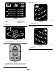
• Keep all parts in good working condition and all hardware tightened. Replace all worn or damaged decals. • Use only accessories, attachments, and replacement parts approved by Toro. Safety and Instructional Decals Safety decals and instructions are easily visible to the operator and are located near any area of potential danger. Replace any decal that is damaged or missing. decal93-6697 93-6697 1. Read the Operator's Manual. 2. Add SAE 80w-90 (API GL-5) oil every 50 hours.
Model 31975 only: decal127-0326 127-0326 3. Remove the key and read the Operator's Manual before performing maintenance. 1. Read the Operator's Manual. decal144-0540 144-0540 1. Height of cut 2. Height of cut Model 31975 only: decal138-7359 138-7359 1. Grease every 50 hours. 2. Belt routing decal144-0541 144-0541 1. Height of cut decal139-6303 139-6303 1. Entanglement hazard—read the Operator’s Manual; stay away from moving parts; keep all guards and shields in place.
Model 31974 only: Model 31974 only: decal144-0542 decal144-0543 144-0542 144-0543 1. Height of cut 1. Height of cut decal137-5949 137-5949 2. Mounting holes 1.
Setup Loose Parts Use the chart below to verify that all parts have been shipped. Procedure 1 2 3 4 5 6 Description Use Qty. No parts required – Debris guard Bracket Rivet Hex-head bolt Washer Height-of-cut pin Shoulder bolt Spacer 1 1 5 2 2 2 2 2 No parts required – Level the cutting unit. No parts required – Grease the cutting unit. WARNING Prepare the machine. Install the debris guard to the front axle. Install the cutting unit to the traction unit. Install the PTO cover.
2 3 Installing the Debris Guard to the Front Axle Installing the Cutting Unit to the Traction Unit Parts needed for this procedure: Parts needed for this procedure: 1 Debris guard 2 Hex-head bolt 1 Bracket 2 Washer 5 Rivet 2 Height-of-cut pin Procedure Procedure Use 5 rivets to install the bracket and debris guard to the front axle (Figure 3). 1.
7. Use 2 hex-head bolts and 2 washers to secure the castor arms to the lift arms (Figure 5). If you have previously used the bolts to install the cutting unit: Apply thread-locking compound to the threads of the bolts. g296657 Figure 6 g296375 Figure 5 1. Lift arm 2. Castor arm 8. 1. Shoulder bolt 2. Spacer 3. Washer 4. Bolt Torque the bolts to the appropriate specification: 3.
Product Overview Specifications Note: Specifications and design are subject to change without notice. g296783 Width of Cut • • Height of Cut Adjustable from 25 to 152 mm (1 to 6 inches) in 13 mm (1/2 inch) increments Net Weight • • Model No. 31974: 1.52 m (60 inches) Model No. 31975: 1.82 m (72 inches) Model No. 31974: 195 kg (430 lb) Model No. 31975: 222 kg (490 lb) Figure 7 1. Jam nuts 3. Height-of-cut chain Attachments/Accessories 2. U-bolt 7.
Operation Note: Determine the left and right sides of the machine from the normal operating position. CAUTION If you leave the key in the ignition switch, someone could accidently start the engine and seriously injure you or other bystanders. Remove the key from the ignition before you do any maintenance. Adjusting the Height of Cut g031661 Figure 8 The height of cut is adjustable from 25 to 152 mm (1 to 6 inches) in 13 mm (1/2 inch) increments. To adjust the height of cut: 1.
Adjusting the Cutting-Unit Pitch Refer to Figure 9 to determine the combinations of spacers for your desired height-of-cut setting. Note: You may use the shims in any combination above or below the castor-arm hub (as required) to achieve the desired height of cut or cutting-unit level. 3. Push the castor spindle through the castor arm. 4. Install the shims (as they were originally installed) and the remaining spacers onto the spindle shaft. 5. Install the tensioning cap to secure the assembly.
1. Park the machine on a level surface, lower the cutting unit, engage the parking brake, shut off the engine, and remove the key. 2. Set the cutting unit to the desired height of cut; refer to Adjusting the Height of Cut (page 11). 3. Check and adjust the front and rear traction-unit tire pressure to the specified tire pressure in the traction unit Operator’s Manual. 4. Check for bent blades; refer to Checking for a Bent Blade (page 19). 5.
Avoid Cutting Too Low If the cutting width of the cutting unit is wider than the mower you previously used, raise the cutting height to ensure that uneven turf is not cut too short. Select the Proper Height-of-Cut Setting to Suit Conditions Remove approximately 1 inch (25 mm) or no more than 1/3 of the grass blade when cutting. In exceptionally lush and dense grass, you may have to slow down the forward speed and/or raise the height-of-cut to the next higher setting.
Maintenance Note: Determine the left and right sides of the machine from the normal operating position. Recommended Maintenance Schedule(s) Maintenance Service Interval Maintenance Procedure After the first 2 hours • Tighten the castor wheel nuts. After the first 10 hours • Check the PTO driveshaft-to-gearbox fastener torque. • Check the lift arm-to-castor arm fastener torque. • Tighten the castor wheel nuts. After the first 50 hours • Change the gearbox lubricant.
CAUTION If you leave the key in the ignition switch, someone could accidently start the engine and seriously injure you or other bystanders. Remove the key from the ignition before you do any maintenance. Greasing the Bearings and Bushings Checking the Lubricant in the Gearbox Service Interval: Every 50 hours Lubricate the grease fittings immediately after every washing.
Every 100 hours Check the torque of the fasteners that secure the PTO driveshaft to the gearbox (Figure 17); refer to the setup section in your machine Operator’s Manual for the appropriate torque specification. g344904 Figure 18 1. Lift arm 2. Castor arm Removing the Cutting Unit from the Traction Unit g299646 Figure 17 1. Gearbox 2. Bolts and nuts 3. Bolt 3. PTO driveshaft 1. Park the machine on a level surface with the cutting unit raised. 2.
1. Park the machine on a level surface, lower the cutting unit, engage the parking brake, shut off the engine, and remove the key. 2. Remove the tensioning cap, spacer(s), and thrust washer from the top of the castor spindle. 3. Pull the castor spindle out of the mounting tube. Allow the thrust washer and spacer(s) to remain on the bottom of the spindle. 4. Insert a pin punch into the top or bottom of the mounting tube and drive the bushing out of the tube (Figure 22).
5. Servicing the Cutting Blades To assemble the castor wheel, push the bearing into the wheel hub. When installing the bearings, press on the outer race of the bearing. Blade Safety A worn or damaged blade can break, and a piece of the blade could be thrown toward you or bystanders, resulting in serious personal injury or death. • Inspect the blade periodically for wear or damage. • Use care when checking the blades. Wrap the blades or wear gloves, and use caution when servicing the blades.
Removing and Installing the Cutting-Unit Blade(s) Check the blades for any wear or damage. The sail lifts the grass up straight, thereby producing an even cut and gradually wears down during operation. Replace the blade if it hits a solid object, is out of balance, or is bent. Always use genuine Toro replacement blades to ensure safety and optimum performance. 1.
4. Examine the cutting edges of all of the blades and sharpen the cutting edges if they are dull or nicked (Figure 27). 10 mm (3/8 inch) lower than the outer blades, proceed to step 7 and add shims between the spindle housing and the bottom of the cutting unit. Note: Sharpen only the top of the cutting edge and maintain the original cutting angle to ensure sharpness (Figure 27). The blade remains balanced if the same amount of metal is removed from both cutting edges. 7.
4. Remove the old belt from around the spindle pulleys and idler pulley. 5. Using a torque wrench or similar tool to hold the idler pulley, route the new belt around the spindle pulleys and idler-pulley assembly as shown in Figure 29. Storage 1. Disengage the PTO, release the traction pedal to the neutral position, and engage the parking brake. 2. Shut off the engine, remove the key, and wait for all moving parts to stop before leaving the operator’s position. 3.
Notes:
Notes:
Notes:
Declaration of Incorporation The Toro Company, 8111 Lyndale Ave. South, Bloomington, MN, USA declares that the following unit(s) conform(s) to the directives listed, when installed in accordance with the accompanying instructions onto certain Toro models as indicated on the relevant Declarations of Conformity. Model No. Serial No.
EEA/UK Privacy Notice Toro’s Use of Your Personal Information The Toro Company (“Toro”) respects your privacy. When you purchase our products, we may collect certain personal information about you, either directly from you or through your local Toro company or dealer.
The Toro Warranty Two-Year or 1,500 Hours Limited Warranty Parts Conditions and Products Covered The Toro Company warrants your Toro Commercial product (“Product”) to be free from defects in materials or workmanship for 2 years or 1,500 operational hours*, whichever occurs first. This warranty is applicable to all products with the exception of Aerators (refer to separate warranty statements for these products).