
Operator's Manual


ProductOverview
g014869
3
9
1
2
4
5
6
7
8
10
11
12
13
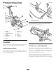
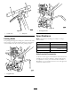
Figure3
1.Handle
8.Starter
2.Throttlelever
9.Cuttingwheel
3.Handlereleaseknob
10.Lift
4.Airlter
11.Beltcover
5.Sedimentcup
12.Fuelcap
6.Fuelvalve
13.Safetybail
7.Choke
Controls
Becomefamiliarwithallthecontrols(Figure3andFigure6)
beforeyoustarttheengineandoperatethemachine.
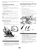
HandleReleaseKnob
Thehandleonthismachinehasthecapabilitytobefolded
downforeasiertransport.Unscrewthehandlereleaseknob
fromthemachine(Figure4).
g014871
1
Figure4
1.HandleReleaseKnob
Foldthehandledowntowardthemachineandscrewthe
knobbackontothehandle(
Figure5).
g014870
Figure5
ThrottleLeverandSafetyBail
Thethrottlelevercontrolstheenginespeed.Withthelever
released,inthedisengagedposition,theenginerunsatidle.
Thisisalsothestartingposition.Whenyoupulltheleverto
thehandle,theenginespeedincreases,thecentrifugalclutch
engages,andthecuttingwheelrotates.
Thesafetybailcontrolstheengine.Holdthesafetybail
againstthehandletodeactivatetheenginekillswitchsothat
theenginewillstart.Releasethesafetybailtostoptheengine.
6