
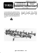
Operator's Manual
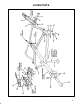


'*! Remove parts from shipping container and lay
out all hardware and fasteners to ease assembly. Use
loose parts chart and illustration to identify and locate
parts.
#"
#"+(!
&)*$$ (, () *' !!$%)*!( +**#&" &#*)
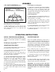
Align holes in stationary (non pivoting) drawbars
with brackets on mower crosstube. Secure each side
with 1/2-13 x 2-1/2" Ig. capscrew, spacer, and
1/2-13 locknut. Position capscrew heads to the inside
of brackets when mounting. Use same procedure on
remaining stationary drawbars.
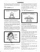
'*! If Spartan mowers are to be attached, drawbar
clamps, part no. 5-1090 and mounting fasteners will
be required to mount drawbar to cross tube of mower
(Fig. 3). Contact your local Authorized Toro Distributor
to order parts or for assistance.
#"+(!
Install lift chain to mower 1/8 x 3/4 cotter pin,
shackle, and 3/8 x 1-1/2 clevis pin.
&)*$$ (#$#&" (%!)
Align mounting holes in trailing frame with holes in
drawbar/cutting unit. Secure with 1/2-13 x 1-1/4" Ig.
capscrews and 1/2-13 locknuts.
Install lift chain from trailing unit to mower with 1/8 x
3/4 cotter pin, shackle and 3/8 x 1-1/2 clevis pin.
Repeat assembly procedure to remaining trailingunits.
Connect trailing units to rear corners of center
frame with U-bolts and 1/2-13 locknuts.
Lubricate all moving parts of frame; refer to
lubrication, page 10.
#"
#"+(!
&)*$$ (, () *' +**#&" &#*)
Align holes in pivoting drawbar with brackets on
mower crosstube. Secure each side with 1/2-13 x
2-1/2" Ig. capscrew, Spacer, and 1/2-13 locknut.
Position capscrew head to the inside of bracket when
mounting. Use same procedure on remaining pivoting
drawbar.
&)*$$ #&" &#*)
Align mounting holes in wing units with mounting
holes in drawbar/cutting units. Secure with 1/2-13 x
1-1/4" Ig. capscrews and 1/2-13 locknuts.
Install lift chains from wing units to mower with1/8 x
3/4 cotter pins, shackles, and 3/8 x clevis pins.
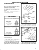
Attach (2) left hand and (2) right hand hinge
sockets to respective sides of center frame with
1/2-13 x 1-1/4" Ig. capscrews and 1/2-13 locknuts.
The ball socket openings should be facing toward the
front of the frame.
Install a grease fitting into each hinge cap.
Install a hinge clamp bolt and lockwasher into each
hinge cap.
Move wing nuts into position so hinge balls are
inserted into hinge sockets.
Position hinge caps over hinge balls and
tightenhinge clamp bolts. Secure hinge clamp bolt with
3/32 x 3/4 cotter pin.
Lubricate all grease fittings and moving parts of
frame members; refer to lubrication, page 10.