
Operator's Manual


5
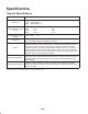
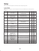
Setup
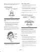
Note: Determine the left and right sides of the machine from the normal operating position.
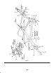
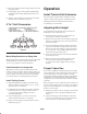
Loose Parts
Note: Use this chart and figure 1 to ensure that all parts have been received. Without these parts, total setup cannot be
completed.
Item No.
Part Description Application 3 Unit 5 Unit 7 Unit
1 Frame support
Supports center frame when not
mounted on tractor
1 1 1
2 Cotter pin, 5/16 x 3” Secures frame support to center frame 1 1 1
3 Drawbar (stationary)
Attaches cutting units to 3 unit center
frame and all trail units
3 3 3
4 Drawbar (pivoting) Attaches cutting units to all wing units – 2 2
5
6
7
Locknut–1/2–13
Spacer
Capscrew, 1/2–13 x 2–1/2
Mounts cutting units to drawbar as-
sembly
6
6
6
10
10
10
14
14
14
8
9
Capscrew, 1/2–13 x 1–1/4
Locknut, 1/2–13
Mounts drawbar assemblies (station-
ary & pivoting) to center frame, wing
and trailing units
12
12
20
20
28
28
10
11
12
Cotter pin
Shackle
Clevis pin, 3/8x1–1/2
Secure lift chains to cutting units
3
3
3
5
5
5
7
7
7
13
14
U–bolt
Locknut, 1/2–13
Connects trailing units to center frame
2
4
2
4
2
4
15
16
Capscrew, 1/2–13 x 1–1/4
Locknut, 1/2–13
Secures center hinge to center frame
–
–
8
8
8
8
17 Hinge socket (left) Mounts left wing unit to center frame – 2 2
18 Hinge socket (right) Mounts right wing unit to center frame – 2 2
19 Grease fitting Mount to hinge cap – 4 4
20
21
22
23
Hinge cap
Hinge clamp bolt
Lockwasher – 1/2”
Cotter Pin – 3/32 x 3/4”
Mount wing units to center frame
–
–
–
–
4
4
4
–
4
4
4
4
24
25
Capscrew, 1/2–13 x 1
Locknut, 1/2–13
Mount wing extensions to wing units
–
–
–
–
12
12
26
27
U–bolt
Locknut, 1/2–13
Mount trailing units to wing extensions
–
–
–
–
2
4
28
29
Pointed hitch pin
Hairpin cotter
Connect hitch to tractor
1
1
1
1
1
1
30 Hitch extension Extends hitch 1 1 1
Operator’s Manual Read before operation 1 1 1
Parts Catalog 1 1 1