
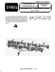
Operator's Manual


$
! -+
-+74)
2716 "-1+ :6)15-215 62 "-1+ 1-65
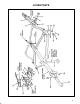
Align mounting holes of right and left wing
extensions with mounting holes in respective wing
units. Secure with 1/2-13 x 1" Ig. capscrews and
1/2-13 locknuts.
156%// 4%9&%45 62 766-1+ 1-65
Align holes in stationary (non pivoting) drawbars
with brackets on mower crosstube. Secure each side
with 1/2-13 x 2-1/2" Ig. capscrew, spacer, and
1/2-13 locknut. Position capscrew heads to the inside
of brackets when mounting. Use same procedure on
remaining stationary drawbars.
156%// 4%-/-1+ 4%0)5
Align mounting holes in trailing frame with holes in
drawbar/cutting unit. Secure with 1/2-13 x 1-1/4" Ig.
capscrews and 1/2-13 locknuts.
Install lift chain from trailing unit to mower
mounting bracket with 1/8 x 3/4 cotter pin, shackle and
3/8 x 1-1/2 clevis pin. Repeat assembly procedure to
remaining trailing units.
Connect trailing units to rear corner of each wing
extension with U-bolts and 1/2-13 locknuts.
Lubricate all moving parts of frame members, refer
to Lubrication, page 10.
#
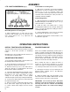
The tractor hitch extension must be installed on all tow
vehicles, to allow frame operation on undulating
terrain.
Mounting holes must be drilled in hitch extension to
accommodate tow vehicle hitch.
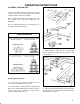
To accommodate varying heights of tractor hitches, the
hitch height can be raised or lowered.
Be sure the frame is located on a level surface and
frame support is adjusted to level frame.
Back the tractor up close to the frame hitch to
gauge the difference in height between the tractor
hitch extension and the frame hitch.
If the frame hitch height must be changed, remove
the capscrews and locknuts securing hitch to frame.
Move hitch to one of the other settings or, if these
settings do not exactly match, a more optimal
adjustment may be achieved by rotating the hitch180_.
Secure tractor hitch extension to frame hitch with
hitch pin and hair pin cotter.
Remove cotter pin securing frame support to frame
hitch, push frame support up through hitch and
re-secure to hitch. Frame support is now in storage
position.
Never exceed 6 MPH (9.66 km/hr) ground speed or
quality of cut will be greatly reduced and damage to the
frame and mowers more likely to occur. Best quality of
cut under most normal conditions is while operating at
approximately 4-6 MPH (6.4-9.66 km/hr). Reduce
ground speed when turning to be sure the outer
mowers do not bounce and skip on the turf.
Before leaving the tractor to adjust the frame or
mowers, be sure the tractor and frame is on a level
surface, the engine is stopped and the parking brake
set. To transport the mowers from one area to another:
Disengage the mower reels by rotating the reel
throwout knobs outward; refer to the Operators
Manual for the mowers.
Grasp the handle grip of the lift handles on the
frame and rotate each handle 1800 forward. This will
raise the mower/s rear roller/s off the ground.
2 126 &%'. 73 64%'624 9-6, *4%0)
%66%',)( * 71-6 0756 &) &%'.)( 73 )%', 64%-/-1+
%1( 9-1+ 71-6 0756 &) 4)028)( %1( 0%17%//;
4)325-6-21)( %-/74) 62 (2 52 9-// 4)57/6 -1 (%0%+)
62 *4%0)