
Operator's Manual


1
SettingUptheStationary
CuttingUnits
Model33145for3CuttingUnits
Partsneededforthisprocedure:
1Framesupport
1Largecotterpin
1
Centerframe
2
Trailingframe
1
Stationarydrawbar
10
Locknut(1/2inch)
2
Spacer
2
Bolt(1/2x2-1/2inches)
4
Bolt(1/2x1-1/4inches)
1
Smallcotterpin
1
Shackle
1
Clevispin
2U-bolt
Procedure
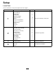
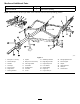
g289135
Figure4
1.Securetheframesupporttothecenterframe
withthelargecotterpin.
2.Alignthebracketsoneachthestationary
drawbarwiththebracketsonacuttingunit
crossbar.
3.Withtheboltheadsfacingtheinsideofthe
drawbar,securebothsidesofthedrawbartoa
crossbarbracketwithabolt(1/2x2-1/2inches),
spacer,andlocknut(1/2inch).
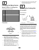
Note:IfyouareattachingSpartancutting
units,drawbarclamps(soldseparately,PartNo.
5–1090)andmountingfastenerswillberequired
tomountthedrawbartocrossbarofthecutting
unit(Figure5).Contactyourlocalauthorized
Torodistributortoorderpartsorforassistance.
g289158
Figure5
1.Drawbarclamp3.Pads
2.Nutpocket
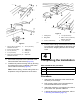
4.Alignthemountingholesinthestationary
drawbartoholesinthecenterframe.
5.Installaliftchaintoeachcuttingunitwithasmall
cotterpin,shackle,andclevispin.
6.Connectatrailingframetobothrearcornersof
thecenterframewithaU-boltand2locknuts
(1/2inch).
6