
Operator's Manual


2
InstallingtheWingFrames
Model33155for5CuttingUnits
Partsneededforthisprocedure:
2
Leftwingframeassembly
2
Rightwingframeassembly
8
Locknut(1/2inch)
8
Bolts(1/2x1-1/4inches)
4
Smallcotterpin
2
Lefthingesocket
2Righthingesocket
4
Greasetting
4Lockwasher
4Hingeclampbolt
4Hingecap
Procedure
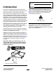
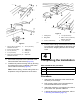
g289136
Figure6
1.Alignthebracketsoneachpivotingdrawbarwith
thebracketsonacuttingunitcrossbar.
2.Withtheboltheadsfacingtheinsideofthe
drawbar,securebothsidesofeachdrawbartoa
crossbarbracketwithabolt(1/2x2-1/2inches),
spacer,andlocknut(1/2inch).
3.Attach2leftand2righthingesocketstothe
respectivesidesofthecenterframewithbolts
(1/2x1-1/4inches)andlocknuts(1/2inch).
4.Installagreasetting,lockwasher,andhinge
clampboltintoeachhingecap.
5.Movethewingframesintopositionsothehinge
ballsareinsertedintothehingesockets.
6.Positionthehingecapsoverhingeballs,tighten
thehingeclampbolts,andsecurethehinge
clampwithasmallcotterpin.
3
InstallingtheTrailingKits
NotIncluded
NoPartsRequired
Procedure
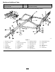
g289159
Figure7
1.Mowingposition2.Trailingposition
Theoptionaltrailinghitchprovidestool-freesnaphook
andattachmentfasteners,usedinplaceoftheU-bolt
attachment.Thisfeatureallowstheframesections
tobeplacedandtrackwithina2.4m(8ft)widthfor
transportpurposesorwhennarrowareasmustbe
mowed;formoreinfocontactyourauthorizedToro
distributor.
1.Locateanddrilltherequiredmountingholesin
thetrailingandwingunitsasshowninFigure9.
2.Installthekitpartstotrailingunitbymounting
thetrailingbartotherearoftheframeswiththe
hingepinand2cotterpins.
Note:Beforedrilling,usethesnaphookasa
templatetoverifytheplacementoftheholes.
7