
Operator's Manual


g289161
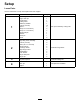
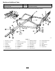
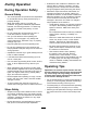
Figure8
1.Drilla1.59cm(5/8inch)
diameterholehere.
6.1.9cm(3/4inch)
2.6.35cm(2-1/2inches)
7.Trailingbar
3.2.2cm(7/8inch)
8.Trailingunit
4.5cm(2inches)
9.Hitchpin
5.Drilla13.5cm(17/32inch)
diameterholehere.
10.Snaphook
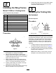
3.Securethesnaphooktotheundersideofthe
framewithboltsandlocknuts(Figure9).
4.Installthekitpartstothewingunitsbysecuring
thetrailinghitchtotheundersideoftheframe
with2boltsandlocknuts(Figure9).
Note:Beforedrilling,usethetrailinghitchasa
templatetoverifytheplacementoftheholes.
g289160
Figure9
1.Trailinghitch
4.7cm(2-3/4inches)
2.Wingframe5.Drilla13.5cm(17/32inch)
diameterholehere.
3.3.5cm(1-3/8inches)6.1.9cm(3/4inch)
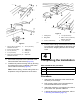
5.Pulltheentiretrailingunitforwardandinsertthe
barunderthe2weldedplatesontheframe;pull
theunitback,snappingthehitchintothesnap
hook.
4
CompletingtheInstallation
Partsneededforthisprocedure:
1Hitchextension
1Hitchpin
1Hairpin
Procedure
1.Attachthehitchextensiontothemachinewith
thehitchpinandhairpin.
2.Drillmountingholesinthehitchextensionto
accommodatethetractionunithitch.
3.Attachthemachinetoyourtractionunit;referto
yourtractionunitOperator’sManual.
4.Lubricateallmovingpartsoftheframe;referto
LubricatingtheMachine(page12).
8