
Operator's Manual
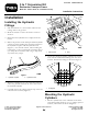


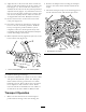


3.Removethe4boltssecuringthecontrolpanel
covertothecontroltowerandremovethecover
(Figure15).
Figure15
1.Controlpanelcover
3.Mountingbolts
2.Controllevers
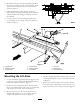
4.Removethelocknutandpivotsecuringthepivot
blockleverstothecontroltower(Figure16).
5.Installthenewpivotblockleversontothepivotpin
whilereinstallingtheexistingpinandtheexisting
blocksintothecontroltower(Figure16).
6.Securetheuppercontrollinkagetubestothepivot
blockswithclevispinsandcotterpins(Figure16).
Coatthepinswith#2grease.
Figure16
1.Uppercontrollinkage
levers
3.Cotterpins
2.Clevispins
7.Reinstallthecontrolpanelcovertothecontroltower
with4bolts(Figure15).
8.Screwthecontrolleversintothepivotblocks.
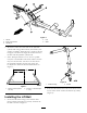
9.Checktomakesurethevalvespoollevers(Figure17)
areinneutral(middleposition)bypivotingthelevers
intowardthevalve,orpullingthemouttondthe
midposition.
Figure17
1.Spoolvalvelevers
2.Mountingpin
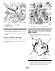
10.Thread7/16inchhexnutsontothelowercontrol
rods.Partiallythreadthelowercontrolrodsintothe
uppercontroltubes(Figure18).Coatthethreads
with#2gungrease.
Figure18
1.Hexnut
3.Cotterpins
2.Lowercontrolrod
6