
Operator's Manual
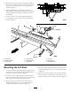


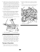


11.Aligntheholeontheendofthelowercontrolrod
Figure18withthemountingpininthecontrolvalve
lever(Figure17).Theleveronthecontroltower
shouldbeinthecenteroftheslot(neutralposition)if
adjustedcorrectly(
Figure19).Threadthelowerrod
intooroutoftheuppercontroltubetoadjust.After
eachleverisadjusted,checktomakesurealllevers
arealignedwitheachother.Readjustifnecessary.
12.Securecontrolrodstocontrolvalveleverswith
cotterpins(
Figure18).
13.Checkthecontrolleveroperationbymovingthe
leverstotheraiseandlowerpositions.Holdthe
lever(s)inrespectivepositionuntilthecycleis
completed.Allleversshouldoperatefreelywith
nobindingandshouldbewelllubricated.Readjust
controltubelinkagesifnecessary.
14.Whenadjustedcorrectly,tightenthejamnutsonthe
lowercontrolrods(
Figure18).
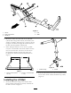
Figure19
1.Leverinneutralposition2.Leverinraiseposition
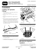
15.Lubricateallthegreasettings.
16.Attachthehydraulichosecouplerstothetowvehicle
andoperatethehydraulicsystem.TheTransport
Framewillberemovingoilfromthetowvehicle
hydraulicreservoir.Donotallowreservoiroillevel
tobedepletedsothatcavitationoccurs.Rell
reservoirwithoilrecommendedfortowvehicleor
useISO68oroilthatissimilartoMobiloil424.
TransportOperation
1.Makesurethatallmowersareinfulltransport
positionbeforemovingtothenextmowingarea.
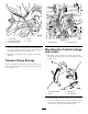
2.Removethehairpincotterssecuringthetransport
strapstothecenterframechannelandliftoffthe
straps.
3.Mountthetransportstrapstothemountingpinson
theliftarmsandsecurewiththehairpincotters.
Figure20
1.Mountingpinsonliftarms
7