
Installation Instructions


g322277
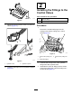
Figure21
1.Mountingtab(control
valve)
4.Link
2.Linkplate
5.Cotterpin
3.Controllever
4.Securethelinktothevalveandleverwiththe
linkplateand2cotterpins(Figure21).
5.Repeatsteps1through4forthecontrolvalveof
cutting-unit7.
10
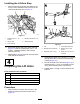
PreparingtheControlRods
Partsneededforthisprocedure:
2
Nut(7/16inch)
2
Control-rodlink
2
Control-rodtube
Procedure
1.Assemblethenut(7/16inch)ontothecontrol-rod
link(Figure22).
g322272
Figure22
1.Control-rodtube3.Control-rodlink
2.Nut(7/16inch)
2.Assemblethelinkandnuttothecontrol-rod
tube(Figure22).
Note:Donottightenthenut.
3.Repeatsteps1and2fortheotherlinkandtube.
11
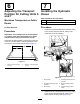
InstallingtheLeverBlocks
Partsneededforthisprocedure:
2Lever
2Leverblock
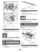
RemovingtheControl-Console
Cover
1.Removethe3knobsfromtheleversofthe
controlconsole(Figure23).
g322285
Figure23
1.Knob4.Flange-headscrew
2.Lever
5.Controlconsole
3.Cover
2.Removethe4ange-headscrewsthatsecure
thecovertothecontrolconsole,andremovethe
cover(Figure23).
10