
Installation Instructions


g321918
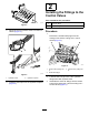
Figure5
1.Tall90°tting
3.Retractport
2.Short90°tting
4.Extendport
4.Assemblethetall90°ttingsintotheextend
portsofthecutting-unit6andthecutting-unit7
controlvalves(Figure5).
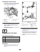
5.Alignthe90°ttingsasshowninFigure6,and
tightenthejamnuts.
g321917
Figure6
1.Short90°tting2.Tall90°tting
3
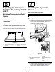
InstallingtheLiftCylinders
Partsneededforthisprocedure:
4
90°tting(3/8inch—tapered-pipethread)
2
Liftcylinder
2
Cylinderrest
4
Capscrew(1/2x1-1/2inches)
4Taperedwasher
4
Flangelocknuts(1/2inch)
4
Spacertube
4
Cotterpin(3/16x1-3/4inches)
2
Lift-armstop
PreparingtheCylinders
Installersuppliedmaterial:#2Permatex™gasket
sealant
1.ApplyacoatofNo.2Permatexgasketsealant
tothethreadsofthe490°ttingswith3/8inch
tapered-pipethreads.
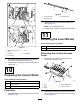
2.Assemblethe90°ttingsintotheextendand
retractportsoftheliftcylinders(Figure7).
g322284
Figure7
preparingtheliftcylinders
1.Liftcylinder(cutting-unit
position7)
3.90°tting(3/8
inch—tapered-pipe
thread)
2.Liftcylinder(cutting-unit
position6)
3.Tightenthe90°ttingsata45°angeltothebody
ofthecylindersasshowninFigure7.
3