
Installation Instructions

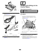


4.Useapieceoftapetomarktheliftcylinders6
and7.
InstallingtheCylinderRest
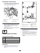
1.Aligntheholesinthecylinderrestwiththe12.7
mm(1/2inch)–diameterholesinthebottomof
thecrosschannels(Figure8)
g322311
Figure8
1.Taperedwasher
4.Flangelocknuts(1/2inch)
2.Capscrew(1/2x1-1/2
inches)
5.Cylinderrest
3.Crosschannel
2.Securethecylinderresttothecrosschannels
(Figure8)withthe2capscrews(1/2x1-1/2
inches),2taperedwashers,and2ange
locknuts(1/2inch).
3.Repeatsteps1and2fortheothercylinderrest
attheothersideofthemachine.
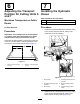
AssemblingtheLiftCylindersto
theMachine
1.Aligntheholesinthe2spacertubesandthe
holesintheangesofthecutting-unit6lift
cylinderwiththe25mm(1inch)-diameterholes
inthetopofcrosschannels(Figure9).
g322309
Figure9
1.Spacertube3.Crosschannels
2.Cylinderbody
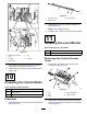
2.Assembletheshaft—25x305mm(1x12
inches)throughthespacertubesandthe
cylinder-bodyanges(Figure10).
g322310
Figure10
1.Cotterpins(3/16x1-3/4
inches)
2.Shaft—25x305mm(1x
12inches)
3.Securetheshafttothecrosschannels(Figure
10)with2cotterpins(3/16x1-3/4inches).
4.Repeatsteps1through3forthecutting-unit7
liftcylinderattheothersideofthemachine.
4