
Installation Instructions


InstallingtheLift-ArmStop
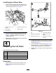
1.Aligntheholesinthelift-armstopwiththe12.7
mm(1/2inch)–diameterholesinthetopofthe
crosschannelsasshowninFigure11.
g322332
Figure11
1.Capscrew(1/2x1-1/2
inches)
4.Flangelocknuts(1/2inch)
2.Lift-armstop
5.Taperedwasher
3.Crosschannel
2.Securethelift-armstoptothecrosschannels
(Figure11)withthe2capscrews(1/2x1-1/2
inches),2taperedwashers,and2ange
locknuts(1/2inch).
3.Repeatsteps1and2forthelift-armstopatthe
othersideofthemachine.
4
PreparingtheLiftArms
Partsneededforthisprocedure:
2Link
2
Shaft—25x102mm(1x4inches)
4
Washer(3/8x1-5/8inches)
4
Lockwasher(3/8inch)
4
Capscrew(3/8x1inch)
Procedure
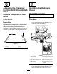
1.Aligntheholesinthelinkwiththeholeinthe
bushinghousingoftheliftarmasshownin
Figure12.
g322276
Figure12
1.Link
4.Lockwasher(3/8inch)
2.Bushinghousing(liftarm)5.Washer(3/8x1-5/8
inches)
3.Capscrew(3/8x1inch)6.Shaft—25x102mm(1x
4inches)
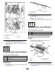
2.Assembletheshaft—25x102mm(1x4inches)
throughtheholesinthelinkandthebushing
housing(Figure12).
3.Securetheshafttothelinkwith(Figure12)2
capscrews(3/8x1inch),2lockwashers(3/8
inch),and2washers(3/8x1-5/8inches).
4.Repeatsteps1through3fortheotherliftarm
andlink.
5