
Installation Instructions


5
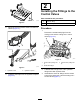
InstallingtheLiftArmsand
DrawBars
Partsneededforthisprocedure:
2
Locknut(3/4inch)
2
Lift-bailpin
2
Capscrew(5/16x3/4inch)
4
Washer(1-1/8x2inches)
2
Shaft—25x102mm(1x4inches)
4
Capscrew(3/8x1inch)
4
Lockwasher(3/8inch)
4
Washer(3/8x1-5/8inches)
2Drawbar
2
Capscrew(1/2x4inches)
2
Locknut(1/2inch)
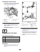
AssemblingtheLiftArmtothe
Machine
1.Aligntheholeinthelift-armtubewiththeholes
inthearmbracketsofthecrosschannels(Figure
13).
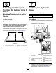
g322274
Figure13
1.Locknut(3/4inch)4.Armbracket(cross
channel)
2.Lift-armtube5.Capscrew(5/16x3/4inch)
3.Lift-bailpin
2.Looselyassembletheliftarmtothecross
channelswith(Figure13)thelift-bailpinandthe
locknut(3/4inch).
3.Aligntheholeinthetabofthelift-bailpinwith
thethreadedholeinthearmbracket(Figure
13),andsecurethepintothebracketwitha
capscrew(5/16x3/4inch).
4.Torquethelocknut(3/4inch)to91to113N∙m
(67to83ft-lb).
5.Repeatsteps1through4fortheliftarmatthe
othersideofthemachine.
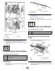
AssemblingtheLiftCylinderto
theLiftArm
1.Aligntheholesinthelink,washers(1-1/8x2
inches),andthettingofthelift-cylinderrod
(Figure14).
6