
Installation Instructions


6
AdjustingtheTransport
PositionforCuttingUnits6
and7
MachinesTransportedonPublic
Roads
NoPartsRequired
Procedure
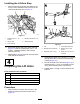
Important:Ifthetransportframeistransported
onapublicroad,theoverallwidthoftheframe
andthemowersmaynotexceed2.4m(8ft).
Adjustthemountingpositionoftheclevisontheend
oftheliftcylindersandthemountingpositionofthe
armstopstothedesiredwidthshowninFigure17.
g012721
Figure17
1.48to51inches(122to
130cm)
2.24-3/4±1-1/2inches(63
±4cm)
7
InstallingtheHydraulic
Hoses
Partsneededforthisprocedure:
2
Hose(long)
2
Hose(short)
Procedure
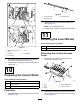
1.Installthelonghosebetweentheshort90°tting
inthecontrolvalveandthe90°ttinginthe
retractportoftheliftcylinder(
g322378
Figure18
1.Hose(short)4.90°tting(retractport—lift
cylinder)
2.90°tting(extendport—lift
cylinder)
5.Short90°tting(control
valve)
3.Hose(long)6.Long90°tting(control
valve)
2.Installtheshorthosebetweenthelong90°tting
inthecontrolvalveandthe90°ttinginthe
retractportoftheliftcylinder(Figure18).
8