
Installation Instructions


3.Repeatsteps1and2forthehosesoftheother
liftcylinder.
8
AssemblingtheTransport
StraptotheMachine
Partsneededforthisprocedure:
1Transportstrap
2Hairpin
Procedure
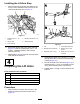
1.Removethe2hairpinsthatsecurethetransport
strapforthecutting-unit4andthecutting-unit
5liftarms(Figure19).
g322288
Figure19
1.Hairpin
2.Transportstrap(5to7
conversionkit)
2.Assemblethetransportstrapofthe5to7
conversionkitontothepinsofthecenterframe
channel(Figure19).
3.Insertthe2hairpinsthatyouremovedin1and
the2hairpinsfromthe5to7conversionkitinto
thestuds(Figure19).
9
AssemblingtheControl
LevertotheControlValve
Partsneededforthisprocedure:
2
Controllever
2
Clevispin
6
Cotterpin
2Linkplate
2Linkplate
Procedure
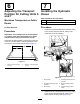
1.Aligntheholeinthecontrolleverwiththeholes
intheforkofthecontrolvalveforcutting-unit6
(Figure20).
g322270
Figure20
1.Cotterpin3.Fork(controlvalve)
2.Controllever4.Clevispin
2.Assemblethelevertotheforkwiththeclevispin
andcotterpin(Figure20).
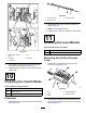
3.Assemblethelinkthroughtheholesinthe
mountingtabofthecontrolvalveandthecontrol
lever(Figure21).
9