Form No. 3364-478 Rev A Reelmaster Transport Frame Model No. 33455—Serial No. 310000001 and Up To register your product or download an Operator's Manual or Parts Catalog at no charge, go to www.Toro.com.
Contents This product complies with all relevant European directives, for details please see the separate product specific Declaration of Conformity (DOC) sheet. Introduction................................................................. 2 Safety ........................................................................... 3 Safe Operating Practices ....................................... 3 Safety and Instructional Decals ............................. 5 Setup...............................................
While Operating Safety • Do not run the engine in a confined area without adequate ventilation. Exhaust fumes are hazardous and could possibly be deadly. • The maximum seating capacity is one person. Never carry passengers. • Sit on the seat when starting the engine and operating the machine. • When leaving machine unattended, put the cutting units either fully up in transport with safety lockup attached, or fully down in mowing position. • Using the machine demands attention.
on both sides of tires and cutting units are fully up or down. Maintenance • Remove the key from the ignition switch to prevent accidental starting of the engine when servicing, adjusting, or storing the machine. • Perform only those maintenance instructions described in this manual. If major repairs are ever needed or assistance is desired, contact an Authorized Toro Distributor. • To reduce a potential fire hazard, keep the engine free of excessive grease, grass, leaves, and accumulations of dirt.
Safety and Instructional Decals Safety decals and instructions are easily visible to the operator and are located near any area of potential danger. Replace any decal that is damaged or lost.
Setup Loose Parts Use the chart below to verify that all parts have been shipped. Procedure 1 2 3 4 5 6 7 8 9 10 Description Use Qty.
Media and Additional Parts Description Use Qty. Parts Catalog Operator’s Manual 1 1 Review the material and save in an appropriate place: Declaration of conformity 1 Certificate of compliance Note: Determine the left and right sides of the machine from the normal operating position.
the following material properties and it meets industry standards. We do not recommend the use of synthetic fluid. Consult with your lubricant distributor to identify a satisfactory product Note: Toro will not assume responsibility for damage caused by improper substitutions, so use only products from reputable manufacturers who will stand behind their recommendation.
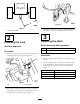
Figure 4 Figure 2 3. Jack frame to desired height, by rotating jack handle clockwise to raise and counterclockwise to lower. 1. Less than 50 inches 3 2 Adjusting the Hitch Installing the Jack Parts needed for this procedure: No Parts Required Procedure 1. Remove jack from storage position by removing pin and sliding jack off storage tube (Figure 3). 2 Hitch Pin 2 Hairpin Cotter Procedure 1. Measure height from ground to top of hitch on tow tractor. 2.
Figure 6 1. Lower control tower 2. Center frame tube 3. U-bolts & flange nuts Figure 5 1. Hitch 2. Bottom mounting holes 3. Middle mounting holes 4. Top mounting holes 2. Mount upper control tower to lower control tower with (2) 3/8 x 2-3/4 inch capscrews and (2) 3/8 inch flange nuts (Figure 6). 3. Secure frame hitch to tractor hitch with hitch pin and hairpin cotter. Note: Adjust height of control tower for operator comfort by using appropriate mounting holes in upper control tower tube.
Figure 8 1. Upper control linkage tubes 2. Clevis pins Figure 7 1. Supply and return hoses 3. Cotter pins 2. Reinstall control panel cover (if previously removed), to control tower with (4) capscrews (Figure 9). 2. Hose hanger 5 Mounting the Control Linkage and Levers Parts needed for this procedure: 3 Control Levers w/Knobs 3 Hex Nut 3 Clevis Pin (5/16 x 1-1/4 inch) 6 Cotter Pin (5/32 x 3/4 inch) Figure 9 1. Control panel cover 2.
sure all levers are aligned with each other. Readjust if necessary. Figure 10 1. Spool valve levers Figure 12 2. Mounting pin 1. Lever in neutral position 5. Thread 7/16 inch hex nuts onto lower control rods. Partially thread lower control rods into upper control tubes (Figure 11). Coat threads with #2 gun grease. 2. Lever in raise position 7. Secure control rods to control valve levers with cotter pins (Figure 11). 8. Check control lever operation by moving levers to raise and lower positions.
3. Couple supply (orange) hose to pressure port of tractor system. 2. Route chains forward, around middle sheaves and outward over side sheaves. 4. It is recommended that a male and female section of the coupling be attached to both tractor and frame. This will prevent reversing the hoses. 3. Secure short lift chains to No. 4 and No. 5 lift arms (rear) with short shackles, clevis pins and cotter pins (Figure 14). Secure to welded ring. 5. Couple return hose to return port or tank on tractor system.
Figure 16 1. Capscrew, spacer tube & locknut 2. Mounting bracket Figure 15 1. Draw bar 2. Lift bail housing 3. Offset hole in draw bar-UP 4. Capscrew and locknut Note: If Spartan mowers are to be attached, draw bar clamps, Part No. 5-1090 and mounting fasteners will be required to mount draw bar to front cross tube of mower. Contact your local Authorized Toro Distributor for assistance. 2. Secure draw bars to lift bails with 1/2 x 4 inch capscrew and 1/2 inch locknut. 2.
5. On remaining mowers, secure lift chains to mower mounting bracket with long shackles, clevis pins and cotter pins (Figure 18). Note: Make sure there are no kinks or twists in chain before installing cutting units. Figure 18 1. 2. 3. 4. Mounting bracket Long shackles Clevis pin & cotter pin Fifth link from mower 5. Spring 6. S-hook 7. Lift bail 6. Hook spring to fifth link in chain from mower and secure other end of spring to lift bail with S-hook (Figure 18).
Product Overview Operation Specifications Note: Determine the left and right sides of the machine from the normal operating position. Note: Specifications and design are subject to change without notice.
on transport frame. Do not restrain tractor valve lever permanently, damage may occur to system. • Raise or lower mowers using control levers. Note: If mowers will not raise or lower, supply (orange) and return hoses may be reversed. Reinstall couplers reversing position. Mark hoses for future identification, or connect a male and female coupler section to transport hoses to prevent reversal.
the previous mowing and prevents operating in the same path continuously. On golf courses, cross cut each end of the fairway at the tee and green to reduce the amount of travel at these locations. Considerable traffic is concentrated in these areas by golfers and carts. Any reduction in travel by the mowing equipment is beneficial to the turf. 8. When mowing around obstacles such as trees, etc., one or more cutting units may be raised to narrow overall width. Transport Operation 1.
Inspection And Clean-up After Mowing At the completion of mowing operation, thoroughly wash the machine with a garden hose without a nozzle so excessive water pressure will not cause contamination and damage to seals and bearings. After cleaning, it is recommended the machine be inspected for possible hydraulic fluid leaks, damage or wear to hydraulic and mechanical components and the cutting units checked for sharpness. Figure 23 1. Mounting hole 2. Lockup bracket 3. Lockup pin 4.
Maintenance Lubrication Apply No. 2 grease to all hydraulic frame fittings and SAE 30 engine oil to all wear or friction points every 50 hours of operation. There are 25 grease fittings on the Transport Frame. Clean the grease fittings with a clean rag prior to greasing to make sure no foreign matter will be forced into the bushings with the lubricant. While applying grease, make certain the bushings are taking grease.
Figure 29 Figure 32 Figure 30 Figure 33 Changing the Hydraulic Fluid Drain and replace the hydraulic system fluid whenever the tractor fluid is changed, if fluid is not compatible with tractor fluid, or if fluid becomes contaminated. 1. Start tractor, remove all cutting units, and raise lift arms until all lift cylinders are fully retracted, then stop tractor. 2. Disconnect supply (orange) and return hose couplers from tractor couplers. 3.
Wheel Bearings To replace the wheel bearings proceed as follows: 1. Jack up the wheel being serviced. Support with jack stand to prevent it from falling. 2. Remove the hub cap, cotter key, slotted nut, and washer (Figure 35). Figure 34 1. Row “A” 2. Row “B” 3. #1 Lift cylinder 5. Disconnect hydraulic hoses connected to back row of control valve, Row "B" (Figure 34). Drain each line and cylinder by carefully pulling down lift arms until all fluid is pumped out of hoses and cylinders and into drain pan.
2. Remove cutting unit. 3. Remove nut from end of pin (Figure 36). Figure 36 1. Lift arm 2. Nut 3. Pin assembly 4. Capscrew 5. Link 4. Remove capscrew from pin assembly. 5. Remove link between hydraulic cylinder and lift arm. 6. Remove pin assembly. 7. Remove bushings in lift arm. 8. Insert and size new bushings and replace pin. 9. Replace capscrew and nut. 10. Reinstall link. 11. Grease bushing with Mobilux #2 grease or equivalent.
Schematics Hydraulic Schematic (Rev.
Notes: 25
Notes: 26
Notes: 27
The Toro Total Coverage Guarantee A Limited Warranty Conditions and Products Covered The Toro® Company and its affiliate, Toro Warranty Company, pursuant to an agreement between them, jointly warrant your Toro Commercial product (“Product”) to be free from defects in materials or workmanship for two years or 1500 operational hours*, whichever occurs first. This warranty is applicable to all products with the exception of Aerators (refer to separate warranty statements for these products).