Form No. 3434-992 Rev A Transport Frame Reelmaster® Model No. 33455—Serial No. 405700000 and Up Register at www.Toro.com.
This product complies with all relevant European directives, for details please see the separate product specific Declaration of Conformity (DOC) sheet. Model No. Serial No. This manual identifies potential hazards and has safety messages identified by the safety-alert symbol (Figure 2), which signals a hazard that may cause serious injury or death if you do not follow the recommended precautions.
Contents Safety Safety ....................................................................... 3 General Safety ................................................... 3 Safety and Instructional Decals .......................... 4 Setup ........................................................................ 5 1 Preparing the Tow Vehicle................................ 7 2 Adjusting the Transport Frame Hitch ................ 7 3 Installing the Control Tower ..............................
Safety and Instructional Decals Safety decals and instructions are easily visible to the operator and are located near any area of potential danger. Replace any decal that is damaged or missing. decal133-8061 133-8061 decal137-6138 137-6138 1. Valve control lever—raise 3. Warning—do not exceed 32 km/h (20 mph). 2. Valve control lever—lower decal137-6139 137-6139 1. Warning—all operators should be trained before operating the machine. 2. Warning—tow vehicle PTO must be greater than 22.
Setup Loose Parts Use the chart below to verify that all parts have been shipped. Procedure 1 2 3 4 5 6 7 Description Qty.
Media and Additional Parts Description Use Qty. Operator’s Manual 1 Read this manual before using the transport frame. Parts Catalog 1 Review the material and save in an appropriate place. Declaration of conformity 1 Certificate of compliance Note: Determine the left and right sides of the machine from the normal operating position.
use products only from reputable manufacturers who will stand behind their recommendation. 1 Material Properties: Viscosity, ASTM D445 Preparing the Tow Vehicle cSt @ 100°C 9.1 to 9.8 Viscosity Index ASTM D2270 Pour Point, ASTM D97 Industry Specifications: No Parts Required Procedure 1. Verify your tow vehicle meets the specifications listed in the table in Specifications (page 14). 2. Determine whether your machine has an open or closed hydraulic system.
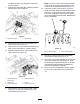
position. Install the ball pin to secure it in the storage position (Figure 16). 2 3 Adjusting the Transport Frame Hitch Installing the Control Tower Parts needed for this procedure: 2 Hitch Pin 2 Hairpin Cotter Parts needed for this procedure: Procedure 1. Measure the height from the ground to the top of the hitch on the tow vehicle. 2. Adjust the transport frame hitch up or down according to the measurement of the machine hitch.
3. 4. Adjust the control tower forward or backward by sliding the tower on the center frame tube and tightening the flange nuts and U-bolts. 2. Secure the upper control linkage tubes to the pivot blocks with the clevis pins and cotter pins (Figure 7). Important: Position the tower in a comfortable position for the operator, within reach. The tower will pitch forward when crossing a ditch or low area in turf. 3. Coat the clevis pins with No. 2 lithium grease.
Note: The lever on the control tower should be in toward the valve, or pulling them out to find the mid position. 7. in the center of the slot (neutral position) if the control rods are adjusted correctly (Figure 11). Coat all pivot points with No. 2 lithium grease or lubricate them with 30 SAE oil. 12. If the lever on the control tower is not in the center of the slot, adjust it by threading the lower rod into or out of the upper control tube.
5 6 Connecting the Supply/Return Hoses to the Tow Vehicle Installing Reelmaster Mowers Parts needed for this procedure: Parts needed for this procedure: 1 Supply hose 1 Return hose 1 Female dust cap 1 Male dust cap 10 Capscrew (1/2 x 3-1/2 inch) 10 Spacer 10 Locknut (1/2 inch) 4 Long shackles 4 Clevis pin (3/8 x 1-1/2 inch) 4 Cotter pin (1/8 x 3/4 inch) 1 Capscrew (3/8 x 1-1/2 inch) 1 Locknut (3/8 inch) 5 Spring 5 S-hook Procedure 1.
2. Secure the lift bracket to #1 lift chain (rear center) with a long shackle, clevis pin, and cotter pin (Figure 13). Note: Ensure that there are no kinks or twists in the chain before installing the cutting units. g012763 Figure 14 g012762 Figure 13 1. Mounting bracket 5. Spring 5. Capscrew and locknut 2. Long shackles 6. S-hook 2. #1 lift chain 6. Spring 3. Clevis pin and cotter pin 7. Lift bail 3. Long shackle 7. S-hook 4. Fifth link from mower 4. Clevis pin and cotter pin 8.
Product Overview Controls Transport Frame Controls Control Levers The controls are conveniently located on the control tower at the front of the frame. g001055 Figure 15 2. Hold the lever(s) in their respective positions until the cycle is completed, then return the lever(s) to neutral. • To raise the mower(s), push the control lever(s) If the tire air pressure is not 165 to 193 kPa (24 to 28 psi), add air to or remove air from the tires. up, to lower the mower(s) push the control lever(s) down.
Specifications Important: After disconnecting the supply/return hose couplers from the tow vehicle valve, always return the tow vehicle hydraulic-directional-control-valve lever to neutral. This deactivates the "remote" hydraulic feature. 2. Note: Specifications and design are subject to change without notice. Tow Vehicle Specification Closed center hydraulic system on the tow vehicle and open center hydraulic system on the transport frame.
Operation 1. Remove the pin from the jack and storage tube (Figure 16). Note: Determine the left and right sides of the machine from the normal operating position. Before Operation Before Operation Safety General Safety • Never allow children or untrained people to operate or service the machine. Local regulations may restrict the age of the operator. The owner is responsible for training all operators and mechanics. g316578 Figure 16 • Become familiar with the safe operation of the 3.
Stowing the Jack • Reduce speed when operating on rough, uneven terrain, and near curbs, holes, and other sudden changes in terrain. 1. Ensure that the transport frame is securely attached to the tow vehicle. 2. Rotate the jack handle to fully raise the jack pad; refer to Figure 17. 3. Remove the pin and rotate the tow bar jack horizontal. Slope Safety 4. Align the hole in the storage tube with the hole in the jack. • Slopes are a major factor related to loss of control 5.
overall efficiency. Mowing at 6.4 to 9.7 km/h (4 to 6 mph) produces the finest turf appearance. Consult the mower operators manual for proper adjustment procedures. 2. When arriving at area to be mowed, remove safety strap and lockup pins and approach area with mowers in transport position. 3. Push the control levers downward to lower the mowers with frame in motion to eliminate possibility of spinning tractor drive wheels on the turf causing turf damage.
• Always inspect the hitch and coupling for wear. Do not tow the machine with damaged or missing hitches or couplings. • Avoid sudden stops and starts. This can cause skidding or jack knifing. Smooth, gradual starts and stops will improve towing. • Avoid sharp turns to prevent rolling. • Chock the wheels to while parked to prevent movement. Raising the Mowers to the Transport Position Note: Before moving to the next mowing area, make sure that all mowers are in the full transport position. 1.
lockup bracket and secure to cylinder rest with hairpin cotter (Figure 21). Inspection And Clean-up After Mowing At the completion of mowing operation, thoroughly wash the machine with a garden hose without a nozzle so excessive water pressure will not cause contamination and damage to seals and bearings. After cleaning, it is recommended the machine be inspected for possible hydraulic fluid leaks, damage or wear to hydraulic and mechanical components and the cutting units checked for sharpness.
Maintenance Recommended Maintenance Schedule(s) Maintenance Service Interval Every 50 hours Maintenance Procedure • Grease the transport frame fittings. • Lightly oil the wear and friction points. Maintenance Safety Lubrication • Before cleaning, servicing, or adjusting the Service Interval: Every 50 hours machine, do the following: Every 50 hours – Park the tow vehicle and machine on a level surface.
g012771 Figure 25 g012774 Figure 27 g012773 Figure 26 g012775 Figure 28 g337510 Figure 29 Oiling the Wear and Friction Points Lightly oil wear or friction points whenever grease fittings are being serviced.
g012768 Figure 30 g012779 Figure 33 Changing the Hydraulic Fluid Drain and replace the transport frame hydraulic fluid whenever the tow vehicle fluid is changed, if the fluid is not compatible with the tow vehicle fluid, or if the fluid becomes contaminated. 1. Start the tow vehicle, remove all cutting units, raise the lift arms until all lift cylinders are fully retracted, and then shut off the tow vehicle. 2. Disconnect the supply and return hose couplers from the tow vehicle couplers. 3.
11. Start the tow vehicle and cycle the lift arms up and down at least 2 full cycles. Check the hydraulic-fluid level with the lift arms raised and add fluid if needed. 12. Install the cutting units. Replacing the Wheel Bearings 1. Jack up the wheel being serviced. Support with jack stand to prevent it from falling. 2. Remove the hub cap, cotter key, slotted nut, and washer (Figure 35). g012776 Figure 34 1. Row “A” 3. #1 lift cylinder 2. Row “B” 5.
10. Reinstall the hub caps. Replacing the Lift-Arm Bushing 1. Position lift arm in the down position. 2. Remove the cutting unit. 3. Remove the nut from the end of the pin (Figure 36). g012778 Figure 36 1. Lift arm 4. Capscrew 2. Nut 3. Pin assembly 5. Link 4. Remove the capscrew from the pin assembly. 5. Remove the link between the hydraulic cylinder and the lift arm. 6. Remove the pin assembly. 7. Remove the bushings in the lift arm. 8.
Schematics g337511 Hydraulic Schematic (Rev.
Notes:
The Toro Warranty Two-Year or 1,500 Hours Limited Warranty Conditions and Products Covered Parts The Toro Company and its affiliate, Toro Warranty Company, pursuant to an agreement between them, jointly warrant your Toro Commercial product (“Product”) to be free from defects in materials or workmanship for 2 years or 1,500 operational hours*, whichever occurs first. This warranty is applicable to all products with the exception of Aerators (refer to separate warranty statements for these products).