Form No. 3316–567 Rev C Reelmaster Transport Frame 5 Unit Model No. 33455—Serial No.
Contents Introduction . . . . . . . . . . . . . . . . . . . . . . . . . . . . . . . . . Safety . . . . . . . . . . . . . . . . . . . . . . . . . . . . . . . . . . . . . . Before Operating . . . . . . . . . . . . . . . . . . . . . . . . . . While Operating . . . . . . . . . . . . . . . . . . . . . . . . . . . Maintenance . . . . . . . . . . . . . . . . . . . . . . . . . . . . . . Safety and Instruction Decals . . . . . . . . . . . . . . . . . Specifications . . . . . . . . . . . . . . . . . . . . . . . . . .
• Sit on the seat when starting the engine and operating the machine. Safety • When leaving machine unattended, put the cutting units either fully up in transport with safety lockup attached, or fully down in mowing position. Hazard control and accident prevention are dependent upon the awareness, concern, and proper training of the personnel involved in the operation, transport, maintenance, and storage of the machine. Improper use or maintenance of the machine can result in injury or death.
• Perform only those maintenance instructions described in this manual. If major repairs are ever needed or assistance is desired, contact an Authorized Toro Distributor. • Before disconnecting or performing any work on the hydraulic system, all pressure in the system must be relieved by stopping the engine and lowering the blower to the ground. • To reduce a potential fire hazard, keep the engine free of excessive grease, grass, leaves, and accumulations of dirt.
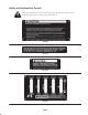
Safety and Instruction Decals Safety decals and instructions are easily visible to the operator and are located near any area of potential danger. Replace any decal that is damaged or lost.
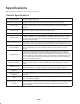
Specifications Note: Specifications and design subject to change without notice. General Specifications Cutting Capacity Main Frame Construction 6.7 acres per hour @ 5.5 MPH. (Assumes no reduction in total area mowed due to overlap, turning, stops, etc.) Tubular and structural steel, bolted and electrically welded construction. Trailer Tongue Tubular and structural steel welded construction. Trailer clevis is adjustable to 3 positions.
Measurements Optional Equipment Length Transport Width Mowing Width Height Tread Width 150” 7’11” w/Reelmaster mowers 14’4” w/Reelmaster mowers 58” (w/Control Tower Collapsed) 68” Transport Ground Clearance 18” Wheel Conversion Kit Part No. 51–3060 Ball Coupler Kit Part No. 53–9760 5–7 Conversion Kit Model No. 33452 7–1/2” Weight 2760 lbs. Shipping Weight (Approx.) 1600 lbs. Setup Note: Use this chart as a checklist to ensure that all parts have been received.
Description Qty. Capscrew 1/2–13 x 3–1/2” Lg. 10 Spacer 10 Locknut 1/2–13 10 Long Shackles 4 Clevis Pin 3/8 x 1–1/2” Lg. 4 Cotter Pin 1/8 x 3/4” Lg. 4 Capscrew 3/8–16 x 1–1/2” Lg. 1 Locknut 3/8–16 1 Spring 5 S–Hook 5 Operator’s Manual 1 Parts Catalog 1 Registration card 1 Use Mount Cutting Units to Drawbars and Lift Bail. Read before operating the machine. Fill out and return to Toro. Note: Determine the left and right sides of the machine from the normal operating position.
7. Adjust tractor drawbar (hitch) so mounting hole is less than 50 inches from outside of rear tractor tire (Fig. 1). This will prevent interference with front cutting unit lift arms. Note: If tractor drawbar cannot be adjusted as described above, use caution when turning, to avoid contact. Figure 3 3. Jack frame to desired height, by rotating jack handle clockwise to raise and counterclockwise to lower. Less Than 50 Inches Adjust Hitch Figure 1 1.
3. Secure frame hitch to tractor hitch with hitch pin and hairpin cotter. 4. Reinstall jack to storage tube on inside of frame channel and secure with pin. Install Control Tower 1. Loosely secure lower control tower to center frame tube with (2) U–bolts and (4) 3/8–16 flange nuts (Fig. 5). Figure 6 1. Supply and return hoses Mount Control Linkage And Levers Figure 5 1. Lower control tower 2. Center frame tube 3. U–bolts & flange nuts 2. Hose hanger 4. Upper control tower 5.
2. Reinstall control panel cover (if previously removed), to control tower with (4) capscrews (Fig. 8). 5. Thread 7/16–14 hex nuts onto lower control rods. Partially thread lower control rods into upper control tubes (Fig. 10). Coat threads with #2 gun grease. Figure 8 1. Control panel cover 2. Control levers 3. Mounting capscrews Figure 10 1. Hex nut 2. Lower control rod 3. Screw control levers into pivot blocks (Fig. 8). 4. Check to make sure valve spool levers (Fig.
7. Secure control rods to control valve levers with cotter pins (Fig. 10). 2. Route chains forward, around middle sheaves and outward over side sheaves. 8. Check control lever operation by moving levers to raise and lower positions. Hold lever(s) in respective position until cycle is completed. All levers should operate freely with no binding and should be well lubricated Readjust control tube linkages if necessary. 3. Secure short lift chains to No. 4 and No.
Install Reelmaster Mowers 3. Secure lift bracket to mower mounting bracket with a 3/8–16 x 1–1/2” lg. capscrew and 3/8–16 locknut (Fig. 16). Use bottom mounting hole in lift bracket. 1. Align holes in drawbar with brackets on mower cross–tubes. Secure each side with 1/2–13 x 3–1/2” lg. capscrew, spacer tube and 1/2–13 locknut (Fig. 15). 4. Hook spring to upper mounting hole in lift bracket and other end of spring to lift bail with S–hook (Fig. 16).
• Tractor hydraulic directional control lever must be actuated simultaneously with control levers on transport frame. Do not restrain tractor valve lever permanently, damage may occur to system. Operation Note: Determine the left and right sides of the machine from the normal operating position. • Raise or lower mowers using control levers. Note: If mowers will not raise or lower, supply/ return hoses may be reversed. Reinstall couplers reversing position.
Important Make sure that no persons are working on or near the mowers before raising or lowering. Caution 4. It usually works best to mow the outer portion of the area first, then work your way to the center. Down shift the tractor prior to climbing a steep incline to eliminate the need to downshift halfway up which could cause tire slippage and turf damage. Do not raise the mowers above halfway while operating on severe hillsides or tractor and frame stability may be affected.
4. Remove hairpin cotter securing lockup pin to center cylinder rest (Fig. 21). Figure 21 Unit shown with 5–7 Conversion Kit installed 1. Hair pin cotter 2. Lockup pins Figure 19 1. Hairpin cotters 3. Cylinder rest 2. Transport straps 5. Slide lockup pin through holes in lockup bracket and secure with hairpin cotter (Fig. 22). 3. Mount transport strap to mounting pins on lift arms and secure with hair pin cotters (Fig. 20). Figure 22 1. Mounting hole 2. Lockup bracket 3. Lockup pin 4.
Inspection And Clean–up After Mowing Caution Never exceed 20 MPH (32 km/hr). Re–duce speed and shift into a lower gear before descending a steep or long grade. At the completion of mowing operation, thoroughly wash the machine with a garden hose without a nozzle so excessive water pressure will not cause contamination and damage to seals and bearings.
Lubrication Apply No. 2 grease to all hydraulic frame fittings and SAE 30 engine oil to all wear or friction points every 50 hours of operation. There are 25 grease fittings on the Transport Frame. Clean the grease fittings with a clean rag prior to greasing to make sure no foreign matter will be forced into the bushings with the lubricant. While applying grease, make certain the bushings are taking grease. Apply lubricant to the fitting until some of the grease comes out from the sides of the bushings.
Figure 31 Figure 29 Figure 32 Figure 30 19
Maintenance Note: #1 cylinder is not connected to a lift arm to aid in draining cylinder. Extend cylinder using a winch or other pulling devise. Note: Determine the left and right sides of the machine from the normal operating position. 6. Connect supply/return hoses to frame control valve. 7. Fill tractor hydraulic fluid reservoir to appropriate level, using correct fluid. Changing Hydraulic Fluid 8. Connect supply/return hose couplers to tractor valve couplers.
3. Pull off the wheel and outer bearing cone. Remove the inner bearing cone and seal from the hub. A slot in the hub is provided so the cone and seal can be removed with the bearing cup. Drive against bearing cup. 4. Clean the hub with a solvent. 5. Press the new cups in the hub, being certain they are fully seated. 6. Pack the new cones with wheel bearing grease. Coat bearing journal and adjacent bearings in hub. 7.
Hydraulic Schematic #1,2,3 LIFT CYLINDER #5 LIFT CYLINDER #4 LIFT CYLINDER CONTROL VALVE SUPPLY LINE “B” WORK PORTS (RETRACT VALVE) “A” WORK PORTS (EXTEND VALVE) RETURN LINE 22
The Toro General Commercial Products Warranty A Two-Year Limited Warranty Conditions and Products Covered The Toro Company and its affiliate, Toro Warranty Company, pursuant to an agreement between them, jointly warrant your 1996 or newer Toro Commercial Product (“Product”) purchased after January 1, 1997, to be free from defects in materials or workmanship for two years or 1500 operational hours*, whichever occurs first.