
Operator's Manual


11
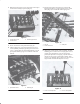
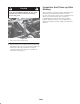
2. Reinstall control panel cover (if previously removed), to
control tower with (4) capscrews (Fig. 8).
Figure 8
1. Control panel cover
2. Control levers
3. Mounting capscrews
3. Screw control levers into pivot blocks (Fig. 8).
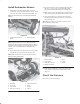
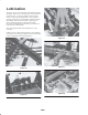
4. Check to make sure valve spool levers (Fig. 9) are in
neutral (middle position) by pivoting levers in toward
valve, or pulling them out to find mid position. Coat all
pivot points with #2 gun grease or lubricate with #30
SAE oil.
Figure 9
1. Spool valve levers 2. Mounting pin
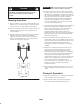
5. Thread 7/16–14 hex nuts onto lower control rods.
Partially thread lower control rods into upper control
tubes (Fig. 10). Coat threads with #2 gun grease.
Figure 10
1. Hex nut
2. Lower control rod
3. Cotter pins
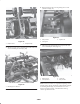
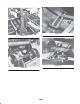
6. Align hole on end of lower control rod (Fig. 10) with
mounting pin in control valve lever (Fig. 9). Lever on
control tower should be in center of slot (neutral
position) if adjusted correctly (Fig. 11). Thread lower
rod into or out of upper control tube to adjust. After
each lever is adjusted, check to make sure all levers are
aligned with each other. Readjust if necessary.
Figure 11
1. Lever in neutral position 2. Lever in raise position